Over time, outdated or non-working stoves are replaced with modern models with advanced functionality. Installing a free-standing device is not difficult - just plug the supplied plug into the outlet. The difficulty arises when choosing a built-in surface. Connecting a user to an induction hob requires basic skills and knowledge. In this review, we will study step by step how to properly connect the device and the basic power requirements.
Wiring and Connection Requirements
The main thing that the owner of an induction hob must understand is that the device consumes a lot of energy. For safe power transport, it is necessary to correctly calculate the cable parameters. The device must only be connected via a separate line. It is carried out from the general panel of the apartment or from the electric meter.
The use of ordinary household sockets to connect the hob is not permitted. The power line is carried out by a copper three-core cable. This can be a modern wire VVGng-Ls (non-flammable, low smoke) or regular NYM. But the main parameter that is calculated for the power line is the cross-section of the cores.
According to existing standards, a 6 sq.m cable is used to connect induction hobs. mm. This is a wire with solid cores. This cable characteristic describes the ideal case. The wire will withstand any load, within the average parameters of the plates, for a long time, without overheating.
There are enough online calculators on the Internet that allow you to calculate cable parameters according to the power of the connected device. It is useful to use these tools when the stove is installed, as they say, once and for all, without the possibility of replacing it with a more powerful one. Or, if you want to save money, select the optimal power line parameters for a specific device.
Approximate cross-section values look like this:
- devices up to 3.5 kW will require a cable with a cross-section of 2.5 sq. mm;
- for furnaces up to 5.6 kW, a wire with a cross-section of 4 sq. mm is suitable;
- power up to 7.2 kW requires a 6 sq. mm cable.
If the stove consumes 40A or higher (the data is indicated in the passport for the device), to connect it you will need a wire with a core cross-section of 10 square meters. mm and above.
But what should those who do not have the opportunity to lay a separate power line to the panel do? That is, it cannot ditch walls or lay cables in any other way? In this case, you will have to connect the stove to the apartment’s regular network. It is important to find out how much power it can handle.
To ensure safe operation of the panel, you will have to accept that it will not operate at full capacity. Most modern devices have the ability to customize modes. The connection is made in compliance with the following rules:
- an emergency shutdown circuit breaker is installed in the panel, which corresponds to the permissible currents (power) of the wiring, and not the panel;
- The panel is programmed so that its maximum currents do not exceed the permissible ones, or the mode of turning on several burners at the same time is blocked.
Another rule that is recommended to be followed when laying the line and connecting the furnace sounds simple: you do not need to lay in too large reserves. This means that for a stove up to 3.5 kW you should not install a 6 sq. mm wire. It may simply not fit into the panel terminal blocks.
RCD selection
The protective automatic installation should be selected in accordance with the level of electricity consumption by the panel. Power is considered the main characteristic of an induction hob. The larger this parameter is, the higher the throughput of the machine you need to buy. It is better to find out all the data in advance. You can do this by opening the instruction manual or asking a sales consultant. When purchasing a circuit breaker, you need to take into account that it will have to protect all wiring elements from possible emergency situations in it. Typically, such switches solve several problems:
- convenience of manual switching of connected circuits and power supplies;
- a completely safe process of passing current in operating mode;
- automatic shutdown in case of emergency.
What kind of socket is needed?
Even if a dedicated power line is not made for the hob, you need to connect the device through a separate outlet. It is placed at a height convenient for inspecting or disconnecting the network. Usually this is no more than 90 cm from the floor. In this case, the socket must not be located above or near the hob.
If, in addition to the stove, a built-in electric oven is installed, the connection point common to both is placed low. That is, at a level below the bottom of the oven. In this case, the outlet should not be mounted close to the floor to avoid short circuits during flooding.
There are also requirements for the parameters of the outlet. Conventional products designed for 16A, even when operating a low-power panel, will be operated at the limit and overheat. There is another difficulty. It is very problematic to insert a 6 sq. mm cable into a regular Euro plug and socket.
It is worth accepting one simple but important rule. Any device with a power above 3.5 kW must be connected through a special outlet. These are products with permissible currents of up to 40 A. If the power of the stove is 8 kW or higher, you will have to find a connector with even greater parameters.
Selecting a location and preparing the hole for installation
It is logical and correct to place the induction hob above the oven. Another recommended place that is suitable for installing the device is the space above the dishwasher.
The further operation of the hob will be determined by how smoothly its surface is installed and how tightly it is secured. There is good ventilation above it, thanks to which it will not overheat. The hood from the panel should be located at a distance of no less than 75 cm. In this case, the back wall of the panel should not come into contact with the nearby vertical edges of objects and there should be a space of several centimeters between them, as well as below.
Necessary equipment and tools
To connect the electrical panel, prepare the following equipment:
- screwdriver, knife;
- connecting cable designed for surface power (4-6 sq. mm);
- adapter clamp;
- tester for checking whether the connection phase matches the wire colors.
The kit usually includes a cable consisting of four main wires, indicating:
- phase (black and brown),
- zero (blue color),
- earth (yellow-green).
Note! The device is connected through a separate RCD circuit breaker, to which no other household appliances are connected.
Useful tips from the master
Helpful tips for connecting your hob
- Carry out installation with joint sealant.
- The socket must be able to withstand the power of the appliance. Otherwise, his work will put you in danger.
- Choose a socket from proven materials, do not skimp on it.
- Clean your panel frequently to prolong its life and prevent damage.
- To connect, draw a separate line.
- Use a multimeter to check the connection.
- When connecting yourself, it is better not to experiment and not pair devices from different manufacturers.
Number of phases
The installation of all new European-made models is designed to connect equipment to a network with a different number of phases. In our homes there are two standards: a three-phase network with 380 V and a single-phase network with 220 V. The choice of the necessary connection diagram depends on the electrical wiring in the house.
The standard hob circuit is represented by a terminal group consisting of five items, marked for convenience with numbers, and one grounding, which is indicated by the icon:
The following symbols are used in electrical engineering:
- phases are designated as L1, L2, L3;
- zeros – N1 and N2;
- grounding marked PE.
Having understood the connection diagrams and wires, you need to study the instructions. The manufacturer's recommendations list all connections and describe in detail the main installation steps. After the selected scheme, we move on to practice.
Electric stove connection cost
Before connecting the electric stove yourself, you should call the service center and ask how much this work performed by a specialist will cost. At the same time, the owner of household appliances gets rid of a lot of problems associated with both time expenditure and the performance of sometimes unfamiliar work.
Typically, a repair shop that carries out electrical installation work undertakes service and warranty repairs of the product.
For example, in Moscow, when performing the entire range of work, standard prices are as follows:
- purchase of necessary materials and components (excluding their cost) – 350.0 rubles per hour of time spent;
- installation and connection of an electrical outlet - 450.0...750.0 rubles per unit (depending on the type of connection);
- installation of electrical wiring with connection to the panel 150.0...350.0 rubles per linear meter;
- installation of an electric stove – 1000.0 rubles.
There are companies that offer to complete the entire range of work on a turnkey basis, without intervention from the owner, for 20.0...50.0 North American dollars. At the same time, the higher price applies to equipment with a glass-ceramic hob.
In the provinces, prices are somewhat cheaper. In Krasnoyarsk and Novosibirsk, the cost of electrical installation and installation starts from 800.0 rubles. In other regional centers, in the Central regions of Russia, many companies offer their services for similar work in the range of 400.0...500.0 rubles.
Connecting the unit to a single-phase network
This type of connection is used when a wire consisting of three cores comes out of the wall. To install the panel, you must complete the following steps.
- Unscrew the metal plate on the back of the panel using a screwdriver.
- Using jumpers (they are supplied with the device), connect the terminals numbered “1”, “2”, “3” and connect the phase wire (brown, black or white).
- Connect the blue wire to the zeros (contacts numbered “4”, “5”).
- Connect the yellow-green wire to the protective terminal.
- Reinstall the device and tighten the screws that secure the connecting cable.
- Check the strength and tightness of the connection, as well as the functionality of the kitchen panel.
Before installing any brands of cooking equipment (panels A eg, Bosch, Siemens, Electrolux, Hansa, Samsung and others) that have a plug on the cable, first check the contacts and power wires inside the socket for compliance. In some devices they are different - in this case we disassemble the socket. We determine the connection compliance using a special multimeter. The wires can be swapped if necessary.
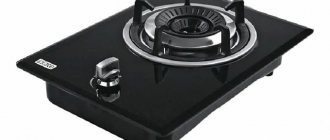
Connecting a gas hob: a set of necessary tools
To install this equipment, you will need the following set of tools:
- graphite pencil;
- silicone sealant;
- adjustable wrench No. 2;
- linen thread;
- multimeter;
- corrugated hose subject to mandatory certification;
- jigsaw
Necessary locksmith tools
The panel should be located in a well-ventilated and ventilated area, with a dew point of no more than 70%. To achieve certain parameters, a supply and exhaust air exhaust system is created, where the amount of required air should be 2 m 3 /h.
Before installation is carried out, the following order of technical measures is performed:
- Select a technological hole in the kitchen set for connecting to gas;
- If the panel has an auto-ignition device, you need to supply power to the device module 220 V, for this you will need:
- jigsaw;
- saw in increments of 1.5–2.0 mm;
- PVSnG wire with a cross section of 2.5–4.0 mm 2;
- conductors according to electrical safety class with degree of protection P1 and double insulation.
PVS wire with a cross section of 3x2.5
- Apply the template to the surface to be cut, following the width, height and seating depth of the hob.
- To correctly cut the hole for the panel, place the template on the countertop and draw its base. Next, carefully cut out the hole using a jigsaw. The next stage is treating the seat with sealant. It will protect the material from moisture.
- Next, place double-sided tape on the surface to be cut and make a line.
- Using a jigsaw, cut a mounting hole to fit the panel. If a standard hole is provided, then no additional measures are required.
- If such measures are necessary, then you need to degrease the cut hole with a soap solution or a special suspension.
- Gas panels are installed on a horizontally flat surface that does not have deviations of more than 2 degrees.
The panel is lowered into the selected hole on the countertop, and, if necessary, the edges are evenly spaced along the gasket along the entire perimeter of the gas equipment.
Connection diagram
The presence of even the slightest thermal gap can cause water and other liquids to enter the oven. This problem may cause power outages. The presence of moisture under the panel can provoke the appearance of pathogenic microorganisms and peeling of the surface.
The surface clamps need to be installed on the adjustment springs so that most of the bracket is under the table top area. Hold the springs in place, use your other hand to tighten the bolts using a screwdriver in the direction of the arrow until they click.
To ensure a tight connection to the gas distribution system, flax is applied to the surface of all threaded connections, both on the hob and on the gas pipe. Gaskets are inserted into the gas hose area if they are provided for in the operating instructions and do not contradict safety measures.
Screw the threaded connections of the hose to the hob and gas pipe, turn clockwise until the nut stops, then tighten with a wrench. Do not apply great force, as this can lead to the paronite or fluoroplastic gasket being pressed through and gas leakage.
Paronite gasket and IFS
The gas panel device has a nominal passage diameter G1/2, which is necessary to connect the device to the gas system. For liquefied gas (propane, butane, isobutane), a tip with a diameter of 9 x 1 mm 2 is screwed onto the end of the hose. The flexible gas line carrying gas must not touch the metal components of the coating.
Connecting the device to a three-phase 380 V network
To install the device, a cable with five cores is used, which has the following parameters: 3 phases, protective grounding and “zero”.
The induction hob should be installed in the following order:
- We connect the 1st phase wire (black, white or brown) to the terminal numbered “1”, the next one to the second number, and the remaining one to the “3” terminal.
- The terminals numbered “4” and “5” are connected with a jumper, and the neutral wire (usually blue) is connected to them.
- We connect a yellow-green wire to the “grounding” terminal marked pe.
Note! The order in which the phase is connected to the contacts of the device is not so important, that is, it makes no difference what color wire the user connects first.
Installing the surface into the countertop, securing it and sealing it
- Inside the box into which the panel will be inserted, markings should be made with a pencil, tracing the inner edges of the device on the back of the tabletop.
- Afterwards, the workpiece is placed face down on the floor and the middle is carefully cut out.
- The edges of the hole are covered with silicone varnish or foil - materials that reduce the possibility of water penetrating under the panel.
- Next, the tabletop is installed in its usual place.
- Adhesive tape is glued to the inside of the induction panel - this is another barrier to moisture. In some cases, plasticine is included instead. It needs to be glued to the tabletop along the cutout and the device installed on top.
All work with cables and the electrical side of the installation in general is followed by installation of the surface in its permanent location in the future. The panel to which the cable and plug are attached is inserted into the hole with a standard mount and pressed on all sides for a more precise fit. Afterwards, be sure to connect the device to the network and check the operation, removing any possible adhesive traces. In the first few hours, there may be some smell of burnt rubber, which is not a defect in the electrical appliance.
Power and power control buttons
When you press the “Network” button for 1 second, the panel turns on. Then, a few seconds after connecting to the power supply, the user will hear a short beep - another indicator of normal operation.
Each of the 4 available cooking zones will be turned on with a button, after which you need to adjust the power level from zero to nine. To activate only one zone, you need to press the button corresponding to it and select the power again.
The induction hob can be controlled electronically, while electric hobs can be adjusted manually. In other words, the housewife can monitor the performance of each of the 4 cooking sectors in real time.
How to connect a plug to a cable
If the plug has four contacts, then when connecting they must be connected to the marked colored wires of the cable. However, there is another option. If the socket is three-pin, a problem arises - four wires when there are 3 pins. The solution is simple - we twist the black and brown wires from the phase together and connect them to the “Phase” contact.
How to turn on an induction cooker correctly
@vestnikao.ru
In the center of the structure there is an induction coil that heats the coil. The turns are wound with a special multi-core wire. An electromagnetic field is formed when an electric current passes through the winding. The eddy currents that are formed provide heating for the burner.
For induction cookware, only cookware made of ferromagnetic alloys is used.
Before turning it on for the first time, be sure to choose a comfortable installation location and clean the surface from possible contamination. The device is connected to the network with a copper wire and the display lights up. The “on/off” buttons are displayed there, by clicking on which you will start the mechanism. Next, the device will allow you to select the functionality that needs to be performed.
Connection problems
If the panel behaves abnormally after the first start-up, for example, turns off and turns on spontaneously, you do not need to immediately worry about incorrect switching. The stove may be childproof. It happens that spilled water on the sensors causes malfunctions. The same thing happens when you start a cold stove in a warm room.
Modern hobs have a pan recognition function. They simply don't turn on unless there is a metal object on the burner.
There are also cases where protection is triggered. For example, when three-phase panels are connected to a regular outlet, some of the burners do not turn on (H is displayed).
Advice on how to avoid problems is quite expected. Before connecting the device, you should carefully study its data sheet and all the manufacturer’s recommendations. With careless installation or an incorrectly calculated power system, the following problems occur.
- Overheating with risk of fire when using conventional 16A sockets for stoves with power above 3.5 kW.
- Incorrect protection system, risk of short circuits and overheating of the wiring. For example, installing only a simple machine without an RCD.
- Danger of short circuits and fire if the cable cross-section is incorrectly calculated, for example, connecting a 7 kW oven with a 2.5 sq. mm wire.
- Switching the panel power line directly to the distribution box in the kitchen.
To summarize, I would like to note that the installation of the hob involves electricity, so during installation you will need certain skills. The safety of people also depends on proper connection. If there is the slightest doubt, it is better to entrust the connection of equipment to professional craftsmen. The same rule applies to eliminating breakdowns of induction cookers. Do-it-yourself repairs are only possible if you have the appropriate knowledge and experience in repairing equipment.
Induction panel wiring
Electrical wiring for the panel must be grounded. It is prohibited to connect the grounding conductor to the working zero, as well as metal pipes and fittings in the kitchen or apartment . By doing this you will not create a grounding loop, but will only expose yourself to danger.
If the apartment does not have a grounding system, then the grounding conductor of the panel power cable is connected to the body of the metal electrical panel (storey or apartment) with a separate clamping screw, if the panel does not have an equipped grounding bus.
Plug and socket for hob
The plug and socket for the hob are purchased as a set. They are recognizable. The operating currents of the circuit for which they are designed are written on the socket body. According to the standards, for panels with a power of 5.9 kW the operating current is 27 Amperes, for panels with a power of up to 7.4 kW this is a current of 34 Amps. The values indicated on the socket body are 2-3 points lower (25 and 32 A).
Important! For safety reasons and to avoid sparking contacts in the socket, you cannot turn off the panel from the socket when the load is on (the panel is operating).
Modes
@imperia-tv.com.ua
All stoves are divided into two large types: with touch and mechanical controls. Each model has its own properties and control features, but the general meaning of control does not change much.
- The “+” and “-” buttons mean adding or subtracting power.
- The digital scale allows you to manually set the value - on the right to increase, on the left to decrease.
- The mechanical regulator allows you to make a choice according to the instructions of the arrows.
Plates from the premium segment have automatic sensors. They work independently, determining the dimensions of the dishes used.
Some stoves have additional modes. For example, maintaining a certain temperature of cooked soup, or slowly heating milk. All the advantages of an induction cooker are described in detail in the instructions for it.
Of particular advantage are stoves that have an emergency shutdown mode. All burners turn off immediately if liquid is spilled on the tile.
Installation instructions
Installation of reinforced components for electric and induction cookers is trusted to specialists. But if you have experience, you can handle it yourself. Installation involves performing the following steps:
- Turn off the power to the cable you will be working with. After a power outage, be sure to check that there is indeed no current in the wire.
- In the selected location, using a puncher, make a hole for the socket cup (for a hidden power socket).
- The power cable is threaded into the socket box and the protective braiding is removed from it. The freed wires are stripped to 0.8-1 cm.
- Connect the wires to the socket mechanism. The yellow-green wire responsible for the “ground” is attached to the central grounding contact. “Phase” and “zero” are connected to the extreme contacts.
- After the wires are secured, the socket box is firmly fixed in the wall using gypsum mortar.
- When the solution dries, the mechanism is secured with screws and the upper insulating housing of the power outlet is installed.
At this point, the installation process is considered complete. Now connect the power and check if the equipment works.
This is interesting:
Connecting the hob and oven to the same outlet and is it possible to do this?
All about retractable sockets for the kitchen
All about sockets on the kitchen apron
Locking and Unlocking
@tehnika.expert
For the safety of small children or animals that like to roam around furniture, there is a locking mode. As a rule, there is a button on the panel with a lock depicted on it. Pressing it completely blocks the control. If you need to cancel an action, you need to press the “+” and “-” buttons simultaneously.
How to connect the 4 wires coming out of the stove and the 3 wires of the electrical wiring power cable
Each core in the cable connected to the plate has a strict functional purpose. In addition, they vary in color. The international standard for color marking of cable cores looks like this:
- brown or black color - phase conductor;
- blue - zero (neutral) conductor;
- yellow-green - grounding conductor.
Any colors other than blue and yellow (often with green stripes) will belong to power or phase lines. With a single-phase network, other power cores are combined into one. Blue is connected to the zero terminal, and yellow-green is connected to the ground terminal.
If the kit includes a cable for two- or three-phase connection, it is not designed for a single-phase version, since in this case the load on the phase wire increases to the total load of all other phases.
In the absence of a terminal box, where the phase conductors are short-circuited with each other, their parallel connection occurs in the plug body. In this case, select a type of plug connector that structurally allows such an operation to be performed.
Another option is to install a standard terminal box with jumpers for phase terminals in the plate housing. In this case, the power cord for single-phase connection is purchased separately, taking into account the increased power of the combined phase conductors.
This is interesting:
Cleaning products for induction hobs
Comparison of the efficiency of induction and gas stoves
What is an induction frying pan and what stove does it fit on?
Operating rules
The surface of the plate is usually made of hardened glass ceramics. It requires some care. In particular, soft wipes and care products for induction devices are used.
The panel must be wiped after each exposure to prevent dirt from settling. Then it will be very difficult to clean it. After washing, wipe dry.
Use properly selected utensils and follow safety precautions. In this case, household appliances will not cause trouble. Do not allow salt and sugar to spill onto the panel. Immediately brush off and wipe the surface.