Today we will look at the repair of the Vektor (Vector) geyser. Below I will present the disassembly procedure with photos, step by step, as I do it.
1. Remove the adjustment knobs from the column. There are three of them here. One knob for adjusting the water flow, a second knob for adjusting the gas supply to the burner, a third knob for turning on the mode of full or partial gas supply to the burner (WINTER/SUMMER mode). We unscrew the screws securing the front panel of the speaker from the bottom and top, disconnect the two connectors of the wires going to the display and remove the front cover.
2. Unscrew the bolts securing the strip with ignition electrodes and ionization electrode from the column burner.
3. Find the bolts that secure the water-gas unit to the column body (4 pcs.) and unscrew them. The bolts on the gas unit side can be unscrewed without any problems. On the water block side, the Chinese column is designed in such a way that the bolts are unscrewed from the wall. If you do this on a workbench, then no problem. If the speaker is hanging on the wall, then you will not be able to do this. Either you will have to remove it, or try to unscrew the two bolts that secure the bracket to the water block, which is not always possible, because Usually the water block is wet from condensation and the bolts rust.
4. Unscrew the right heat exchanger tube from the water block (2 bolts on the coupling flange). We unscrew the two screws on the brackets that secure the burner, disconnect the ground wire screwed to the gas block (yellow wire). We disconnect all connectors: microswitch connector, gas valve connector, wires going to the battery compartment.
5. Remove the entire water-gas block from the column along with the burner. It’s also a good idea to unscrew the plug to drain the water from the water block. It is long and will interfere with both disassembly and assembly of the Vektor (Vector) geyser.
6. Now our task is to remove the heat exchanger from the column body. To do this, unscrew the three screws that secure the heat exchanger from below to the rear panel of the column housing, disconnect the draft sensor from the column cap and the temperature sensor from the heat exchanger, unscrew the 2 screws that secure the column cap to the housing (at the very top). All we have to do is disconnect the hot water pipe of the heat exchanger from the body, which is attached from below with two self-tapping screws. The heat exchanger and cap can be removed from the housing. Next, unscrew the 4 screws connecting the column cap and the heat exchanger. The column itself is disassembled into units. Only the ignition unit remains in the housing.
7. Next, we will consider disassembling the water block of the gas water heater. We unscrew the 4 bolts on the body, disassemble the block and remove the membrane. Chinese gas water heaters usually have 2 types of water blocks. This column contains a “large” water block with two “ears” (in common parlance). Usually the column does not light up or heats up poorly precisely because of this membrane. I definitely recommend changing it if you disassemble the water block.
8. There is one more part of the water unit, which I definitely advise you to change, even if it is working properly at the moment. We are talking about the stuffing box assembly of the rod. It is unscrewed from the body of the water block and replaced entirely. No one replaces the rings separately (they are pressed in). This part is a consumable and is often the cause of column failure. Usually, if the stem seal leaks, water drips onto the microswitch, it fails, and the column does not turn on at all. Let's say you replaced only the membrane in the block and decided not to change the rod with the stuffing box assembly. What will happen next? Often events unfold like this: a new elastic membrane begins to work at full strength and push the rod much further than before the repair. Dirt and rust have already accumulated on that part of the rod, which quickly kills the already hardened rubber ring of the oil seal, as if it were being scraped with sandpaper. The oil seal begins to leak and you will have to climb to disassemble the water block of the gas water heater again. And this is not the worst possible scenario! The worst thing is that a rusty rod can seize. Then the column will simply continue to work when you turned off the water (it will not turn off). It's very scary! Although the column is equipped with an overheating sensor, as long as it works, anything can happen. God forbid that only the column will suffer and not be scalded by the steam.
Dear buyer.
You purchased a gas instantaneous water heater with an electronic device
vom, allowing it to be automatically ignited when the hot water tap is opened.
The device has a digital indicator that allows you to control the temperature
heating cycle of water flowing from the tap (only for model JSD20-W).
Thank you for choosing our water heater. When purchasing a device, check the completeness and also ask for the completed
supply of coupons for warranty repairs by the trading organization.
This instruction manual contains installation information
device, rules of use and maintenance, safety measures during operation of the device, compliance with which will ensure long-term trouble-free and safe operation of the product. Please read it carefully and follow the instructions contained therein.
VEKTOR water heaters have all the necessary certificates and are approved
Installation of the device, instructing the owner on the principles of operation and rules
operation of the device, maintenance is carried out by the operating organization of the gas industry or other organizations that have a license
for this type of activity.
Checking and cleaning the chimney, repairing and monitoring the plumbing system
Geyser Vector JSD 11-N
Grigory
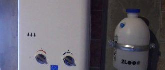
An excellent speaker for a summer house, since this model simply does not need a chimney. Due to the low productivity of combustion products, so little is released that they can be released directly into the atmosphere. Just in case, we ventilate the room later. We are also pleased with the small size of the dispenser and the ability to connect bottled gas, which our neighbors in the dacha area were happy about - they don’t have gas in their house, but they live in the dacha all summer. Now they, too, are happy to have hot water and the opportunity to swim or wash dishes under warm water. If the water heater didn’t go out when the water pressure changes (at the dacha the pressure constantly fluctuates), then it would be doubly wonderful. But overall we are satisfied.
Advantages:
- There is no need for a chimney, which is important for a small country house;
- Large temperature adjustment range;
- Possibility of operation from bottled gas, and parts for connecting the bottle do not need to be purchased separately - everything is included in the kit.
Flaws:
- Sometimes it goes out, but this is due to pressure changes - nothing can be done about it;
- There is no temperature indicator, you have to adjust the heating by touch.
Safety instructions, 1 safety instructions
SAFETY INSTRUCTIONS
For your own safety and to avoid damage to the device, it is prohibited:
a) independently install and put the device into operation; b) use the device in the absence of draft in the chimney; c) use a faulty device; d) independently disassemble and repair the device; e) make changes to the design of the device; f) leave a working device unattended; g) touch the lining in the area of the viewing window during operation of the device and
in the immediate vicinity of it, as well as to the exhaust pipe of combustion products near the gas exhaust device of the apparatus, because heating temperature can reach 100 C.
To avoid carbon monoxide poisoning, the device must be installed according to the design in a well-ventilated room, where the grilles or the gap at the bottom of the door or wall should not be tightly closed. When installing the device in an unheated room in winter, it is necessary to drain the water from it. During normal operation of the device and if the gas pipeline is in good working order, there should be no smell of gas in the room. IF YOU SMELL GAS:
a) close the gas supply valve located on the gas pipeline in front of the device; b) open windows and doors to ventilate the room, ensuring maximum
fresh air flow;
c) do not turn on or off electric lights or any electrical appliances.
d) do not use open flames (lighters, matches, etc.); e) don't smoke; f) immediately call the emergency gas service by phone. 04
.
If a malfunction is detected in the operation of the device, you must contact
gas service and do not use the device until the faults are eliminated.
During normal operation of the device, when closing the hot water tap, the main
the relay should go out.
If after closing the hot water tap the main burner continues
burn, you must turn off the gas supply to the burner using the gas shut-off valve installed in front of the device and call the gas service.
If you use a faulty device or if the above operating rules are not followed, poisoning may occur with gas or carbon monoxide (CO) contained in the products of incomplete combustion of gas, and can also lead to a fire. The first signs of poisoning are: heaviness in the head, palpitations, tinnitus, dizziness, and general weakness. Then nausea, vomiting, shortness of breath, and impaired motor function may appear. The victim may suddenly lose consciousness. To provide first aid you need:
take the victim to fresh air;
unbutton clothing that restricts breathing;
give ammonia a sniff;
Instructions for the Vektor JSD20 water heater
3 INSTALLATION PROCEDURE
3.1 Installation location
3.1.1 The device must be installed in kitchens or other non-residential heated premises in accordance with the gasification project and SNiP 42-012002.
3.1.2 The volume of the room where the water heater is installed must be at least 8 m3.
3.1.3 When the device operates, oxygen is burned in the room. Therefore, it must have a window with a window (an opening transom) for a constant flow of fresh air while the water heater is operating.
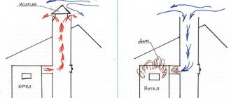
as close as possible to the chimney (installation requirements are set out in paragraph 3.6). One of the available methods for checking the presence of draft in a chimney is shown in the figure. |
3.1.5 It is prohibited to install the device above a source of heat or open flame (for example, above a gas stove, electric heating devices).
3.2 Installation of the device
3.2.1 Before installing the device, you must obtain permission from the competent gas service organization.
3.2.2 Installation of the device must be carried out by the operating organization of the gas industry or other organizations licensed for this type of activity.
3.2.3 The installed device must be registered with the gas service.
3.2.4 The device must be installed on fireproof walls (brick, concrete, lined with ceramic tiles).
3.2.5 It is prohibited to install the device on a wooden wall (partition).
3.2.6 Before installing the device on a wall made of non-flammable material, it is necessary to first install insulation consisting of a galvanized sheet with a thickness of 0.8... 1 mm over a sheet of basalt thermal insulating cardboard BTK with a thickness of 3.5 mm. The insulation must protrude beyond the dimensions of the device body by at least 100 mm on each side.
The distance from the side surfaces of the apparatus to non-flammable walls without the use of thermal insulation must be at least 250 mm. If the specified distance is reduced to 150 mm, it is necessary to install thermal insulation.
3.2.7 To carry out service maintenance when installing the device, the following clearances must be maintained:
— the distance from the side surface of the apparatus to the side wall is at least 150 mm;
— the free space in front of the front surface of the device must be at least 600 mm.
3.2.8 The device is hung on brackets fixed in the wall (included with the product), using mounting holes on the frame.
3.2.9 It is recommended to install the device at such a height that the viewing window is at eye level of the consumer.
3.2.10 Overall and connecting dimensions for connecting pipelines for gas supply, water supply and drainage, and combustion products removal through the gas exhaust pipe are shown in Fig. 3.
3.2.11 Shut-off valves for water and gas supply installed in front of the apparatus must be easily accessible.
3.3 Water connection
3.3.1 To increase the service life of the device and improve its performance characteristics, it is recommended to install a water purification filter in front of the device.
t~h and and __
In regions with hard water, it is recommended to install water softeners in front of the appliance.
3.3.2 Connect the device to the water supply network using pipes or flexible hoses with an internal diameter of at least 13 mm and a hose length of no more than 1.5 m.
3.3.3 Connecting cold and hot water pipelines should not be accompanied by mutual tension of pipes and parts of the apparatus in order to avoid displacement or breakage of individual parts and parts of the apparatus and violation of the tightness of the water system.
3.3.4 Before connecting the water heater to the water supply network, it is necessary to drain the water from the pressure pipeline to prevent possible unwanted entry of dirt and deposits into the device when it is first turned on.
3.3.5 After connecting the pipelines to the device, it is necessary to check the tightness of the joints by first filling the internal cavities of the device pipeline with water. Checking the tightness is done by opening the cold water shut-off valve (with the water taps closed). Leakage at the joints is not allowed.
3.3.6 Rules for installing the device using flexible hoses
Flexible hoses used to connect gas and water must have a certificate of conformity, which must indicate the technical conditions for delivery, their scope of application, service life and technical characteristics.
After the service life specified in the certificate has expired, the hose must be replaced.
When connecting the device using flexible hoses, you must follow the installation rules, which do not allow:
— twisting of the hose relative to the longitudinal axis;
— installation of a hose with a bend near the tips. The length of the section of the hose at the seal, which should not be subject to bending, must be at least 50 mm. The minimum permissible bending radius of the hose, measured along the external generatrix, must be 90 mm (see Fig. 4).
| Rice. 4. Requirements for installation of flexible hoses |
Recommended:
1) use corner connections and adapters to avoid kinks in the hoses near the tips.
2) use intermediate supports when installing long hoses:
3) if installed in a straight line, install hoses with slack. Recommended hose installation diagrams are shown in Table 3.
3.3.7 Installation of the hose must begin with the fixed elements of the hose having cylindrical pipe threads.
This requirement does not apply to a connection whose mating part is a union nut.
3.3.8 The sealing of the threaded connection of the fitting with the mating part (radial connection) must be done using tape fluoroplastic sealing material (FUM) or sealant.
3.3.9 The threaded connection of the union nuts (end connection), both movable and fixed, with the mating fitting must be made using gaskets.
The gasket material is oil- and petrol-resistant rubber, paronite or fluoroplastic-4.
3.3.10 After connecting the water and testing the pipeline, it is necessary to check the functionality of the electronic ignition of the burner, for which:
— insert batteries into the battery compartment, observing the polarity. Failure to comply with this condition will result in the electronic unit not operating;
— open the hot water tap, and a continuous electronic discharge should occur between the electronic spark plugs and the burner section, which indicates the functionality of the electronic unit and the correct installation of the electronic system.
If there is no discharge, carefully check the reliability of the system installation according to the electrical connection diagram (see Fig. 2).
Table 3 Rules for installing flexible hoses
3.4 Gas connection 3.4.1 To ensure stable operation of the device, it is necessary
make gas line connections with metal pipes with an internal diameter of at least 13 mm or flexible hoses with Dу = 13 mm, at least, and a length of no more than 2.5 meters.
3.4.2 When installing gas pipelines, the number of dismountable connections must be kept to a minimum.
3.4.3 Flexible hoses for gas supply, in accordance with the requirements of SNiP 42-01-2002, must be resistant to the supplied gas at specified pressures and temperatures.
3.4.4 The rules for connecting gas using flexible hoses are similar to the rules set out in paragraphs. 3.3.6 and 3.3.7.
3.4.5 When installing a gas line to the device, it is necessary to install a shut-off valve at the entrance to the device.
3.4.6 Connecting a gas pipe should not be accompanied by mutual tension of pipes and parts of the apparatus in order to avoid displacement or breakage of individual parts and parts of the apparatus and violation of the tightness of the gas line.
3.4.7 After connecting the device to the gas line, the connections between the device and communications must be checked for leaks.
3.4.8 Checking the tightness at the gas supply connections is carried out with the device not working and the shut-off valve in front of the device open.
Tightness control is carried out by washing joints or other safe methods. The appearance of bubbles means a gas leak. Gas leakage is not allowed.
3.5 Connecting the device to a liquefied gas cylinder
3.5.1 Before connecting the device to a liquefied gas cylinder, make sure that your device is configured to work with liquefied gas.
3.5.2 The liquefied gas cylinder must be equipped with a reducer designed to stabilize the pressure at 300 mm water column. and gas flow rate of at least 20 l/min.
3.5.3 After connecting the liquefied gas cylinder, it is necessary to check the connections for leaks in accordance with clause 3.4.8.
3.6 Installation of a chimney to remove combustion products
3.6.1 The most important condition for safe operation of the device is the removal of all combustion products of gaseous fuel. Therefore, the rules described below for connecting the exhaust gas pipe to the chimney must be strictly followed.
The chimney must be sealed and resistant to combustion products. Resistance to combustion products means resistance to thermal loads and resistance to combustion products. The draft in the chimney should be in the range from 2 to 30 Pa.
The gas exhaust pipe must be made of heat-resistant and corrosion-resistant materials, such as: stainless steel, galvanized steel, enameled steel, aluminum with a wall thickness of at least 0.5 mm.
You need to make sure that there is really good draft in the chimney (see picture on page 15).
Do not use ventilation ducts to remove combustion products. The exhaust pipe must be connected to the chimney as quickly as possible (the maximum permissible distance of the exhaust gas pipe from the chimney is 2 m). The exhaust pipe should have a slight slope (2°) upward towards the location
connections with the chimney.
The exhaust pipe must have an internal diameter of at least 110 mm.
For reliable removal of combustion products, the minimum length of the vertical section
the chimney must be at least 500 mm.
The connection of the device with the gas exhaust pipe must be sealed, Fig. 5. 3.6.2 The connection option for the exhaust pipe is shown in Fig. 5
Rice. 5 Connecting the exhaust pipe to the device |
4 USING THE MACHINE
The device is configured for a specific type of gas, indicated on the plate on the device.
4.1 Turning on the device
4.1.1 Before turning on the device, open the battery compartment and install the batteries, observing the polarity;
4.1.2 To turn on the device you must:
1) open the cold water shut-off valve installed in front of the entrance to the apparatus, while the hot water tap must be closed;
2) open the shut-off valve on the gas pipeline in front of the device;
3) open the hot water tap. During the flow of water, a spark discharge should occur between the ignition electrodes 12 and the burner 7 (see Fig. 1).
When first turned on, due to the presence of air in the gas pipeline as a result of installation of the apparatus, ignition of the burner may occur after 1-2 minutes.
Because the spark discharge lasts a short time after turning on the water; to re-form the spark discharge, you need to close the water and then open it. And repeat this until the air is completely released, until the burner ignites; If the burner does not ignite, turn knob 4 to the extreme right position, this will allow the burner to ignite at low water pressure in the system.
4.2 Adjusting the degree of water heating
4.2.1 Adjustment of the degree of water heating is carried out using one of the following methods:
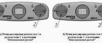
— to obtain the maximum amount of warm water, you need to set knob 4 to the extreme right position, and turn knob 5 to achieve the required heating temperature;
— by turning knob 5 of the gas regulator (changing the gas supply to the main burner);
- changing the flow of water passing through the device using a hot water tap installed at the outlet of the device.
- using a mixer, adding cold water until the required temperature of the water flowing from the tap is obtained.
4.2.2 If the water in the water supply is soft, you can use any of the above methods to dilute hot water.
4.2.3 With hard water, it is not recommended to use a water mixer to dilute hot water, since overheating of water in the heat exchanger leads to faster scale formation in the heat exchanger pipes and their clogging. In this case, the amount of scale formed is proportional to the increase in the temperature of the water leaving the apparatus.
RECOMMENDATIONS. With hard water, to increase its service life, it is recommended to clean the heat exchanger (see paragraph 5.3.3) every six months.
4.2.4 To reduce the intensity of scale formation, it is necessary to set the gas regulator knob to a position that ensures water heating no higher than 60 0C. The formation of scale in the heat exchanger over time can lead to a decrease in the temperature of the heated water and a weakening of the hot water stream.
All other methods of regulating the temperature of hard water are acceptable.
4.2.5 Having set the required water temperature, you don’t have to use knobs 4 and 5, because turning the burner on and off is ensured by opening or closing the hot water tap.
4.3 Turning off the device for a long time
4.3.1 When you finish using the device (at night, for a long time away from home, etc.), it must be turned off, following the following sequence:
— close the hot water tap;
— close the gas shut-off valve at the entrance to the apparatus;
— close the cold water shut-off valve.
4.3.2 After finishing using the device with hard water, you must:
- open the hot water tap
— set handle 5 to the extreme right position;
— pass water through the apparatus until warm;
— close the gas shut-off valve at the entrance to the apparatus;
— close the cold water shut-off valve at the entrance to the device.
4.4 Frost protection
4.4.1 If, after turning off the device, the water in it may freeze, then it is necessary to drain the water from the device as follows:
— close the gas shut-off valve and the water shut-off valve in front of the device;
— open the hot water tap;
— unscrew the drain plug 22 (see Fig. 1);
- drain the water;
— screw in plug 22 until it stops and close the hot water tap.
5 MAINTENANCE
To ensure long-term, trouble-free operation of the device and maintain its performance characteristics, it is necessary to carry out regular inspection, care and maintenance.
To ensure fire safety, it is necessary to carefully monitor the cleanliness of the burners and avoid a smoky flame when burning gas, which leads to soot deposits on the heat exchanger. In this case, the gaps between the fins of the heat exchanger become overgrown with soot, as a result of which the flame is thrown out of the combustion chamber, which can lead to a fire.
Inspection and maintenance are carried out by the owner of the device.
Checking and cleaning the chimney, repairs and monitoring of the water supply system are carried out by the owner of the device or the house management.
Maintenance of the device is carried out by gas service specialists or other organizations licensed for this type of activity at least once a year.
Work related to maintenance is not a warranty obligation and is carried out at the expense of the consumer.
5.1 Inspection Every day before turning on the device:
- should not smell gas. If you find it, contact the gas service;
— check that there are no combustible objects near the device.
— after turning on the device, it is necessary to check the combustion pattern of the burner through viewing window 17: the flame should be blue and not have yellow smoky particles
From £99
tongues indicating clogging of the manifold and internal channels of the burner sections.
Remember!
Due to clogging of the internal channels of the burner sections, an insufficient amount of air is supplied, which is necessary for the normal operation of the apparatus, which leads to incomplete combustion of the gas, which, in turn, leads to the following phenomena:
- possibility of poisoning, because incomplete combustion produces carbon monoxide;
— deposition on the surface of the heat exchanger and on the side surfaces of the combustion chamber of soot, which is formed during incomplete combustion of gas. The presence of soot greatly impairs the operation of the device.
5.2 Care
5.2.1 The device should be kept clean, for which it is necessary to regularly remove dust from the top surface of the device, and also wipe the lining first with a damp and then a dry cloth. In case of significant contamination, first wipe the lining with a wet cloth moistened with a neutral detergent, and then with a dry cloth.
5.2.2 It is prohibited to use strong detergents containing abrasive particles, gasoline or other organic solvents to clean the surface of the cladding and plastic parts.
ATTENTION!
All maintenance operations on the device should be performed only after it has been completely switched off.
5.3 Maintenance
During maintenance the following work is performed:
— cleaning the burner;
— cleaning water and gas filters;
— cleaning the heat exchanger from scale in the internal cavity and from soot on the outer surface (if necessary);
— replacement of sealing connections in gas and water systems;
— checking the tightness of the gas and water systems of the device;
— checking the operation of sensors for draft and water overheating;
— lubrication of moving joints (if necessary).
1 Cleaning the burner To clean the burner, perform the following operations:
— turn off the device;
— turn off the gas supply valve, remove the lining, remove the burner;
— use a brush to remove dust from the outer surfaces of the burner and from the collector;
— wipe the collector and nozzles with a damp cloth;
— use a brush to remove dust from the internal channels of the burner sections;
- wash the burner with soapy water, especially its internal cavities using a brush. Rinse thoroughly with running water, dry and put back in place.
Keeping the burner constantly clean will eliminate soot contamination from the heat exchanger and increase its service life.
2 Cleaning water and gas filters
Remove the water and gas filters. Clean them using a jet of water and a brush. Dry the gas block filter. Reinstall the filters.
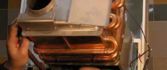
3 Cleaning the heat exchanger
If the heat exchanger is dirty, it is necessary to clean its outer surface when soot has formed on it, and the inner surface of the heat exchanger pipes when scale has formed in them. To remove contamination from the outside you need to:
- remove the heat exchanger and immerse it in a hot solution of soap or other synthetic detergent.
— keep it in the solution for 10-15 minutes and clean the upper and lower surfaces with a soft brush. Rinse with strong water jet.
- If necessary, repeat the entire process. To remove scale you need to:
— remove the heat exchanger and place it in a container;
— prepare a 10% solution of citric acid (100 g of powdered citric acid per 1 liter of warm water);
— pour the prepared solution into the heat exchanger pipeline. Leave the solution for 10-15 minutes, then drain and rinse the pipeline thoroughly with water;
- If necessary, repeat the entire process.
4 Replacing sealing joints
During maintenance, when dismantling and reassembling water and gas communications, it is necessary to install new seals.
5 Checking the tightness of the gas and water systems of the device
After the next maintenance, when gas and water communications were dismantled, it is necessary to check the device for leaks (see paragraphs 3.3.5 and 3.4.8).
6 Checking the performance of the draft sensor
To check the draft sensor, it is necessary to remove the gas exhaust pipe, turn on the device and, under normal operating conditions (with the gas tap fully open and nominal water flow), close the gas pipe of the device with a metal sheet. After 10...60 seconds the device should turn off.
If the device does not turn off, bend the sensor into the gas outlet device 11 and repeat the test.
After checking, install the gas exhaust pipe in place, ensuring the connection is tight.
7 Checking the functionality of the heat exchanger overheat sensor
To check the heat exchanger overheating sensor, it is necessary to turn on the device in the nominal operating mode (with the gas tap fully open and the nominal water flow), then set the minimum possible water flow at the maximum power of the device (control knob 5 should be in the extreme right position). When the maximum temperature indicated on the sensor is reached, the device should turn off.
8 Extraordinary cleaning of the device
Cleaning the device may be required more often than once a year if the device is used intensively in a room where the air contains a lot of dust. This can be determined visually by the changed color of the apparatus burner flame. If the flame turns yellow or smoky, this indicates that the burner is
has become clogged with dust particles from the air, and the device needs to be cleaned and maintained. Normally the flame should be blue. Extraordinary cleaning of the device must also be carried out if construction or repair work was carried out in the room where the device is installed and a lot of construction dust and debris got into the device.
9 POSSIBLE DEVICE MALFUNCTIONS AND METHODS
THEIR ELIMINATIONS
Possible malfunctions of the device and methods for eliminating them are given in Table 4.
Before you begin repairing the water heater, check the battery charge level and the electrical contacts of the battery compartment.
______________________________________________________________ Table 4
| Name of faults | Probable Cause | Elimination methods |
| The device does not turn on: — when opening hot water, there is a spark discharge, the device does not turn on — when opening hot water there is no spark discharge | The gas shut-off valve in front of the device is closed Weak water pressure in the water supply network Weak water pressure at the outlet of the device while normal at the inlet. — the filter at the inlet to the device or the filter in the faucet mixer may become clogged — presence of scale in the heat exchanger when using hard water Water regulator handle 4 (Fig. 1) is set to the extreme left position. The water pressure at the inlet to the device is not enough to operate the water regulator There are no batteries in the battery compartment | Open the gas shut-off valve in front of the device Call a plumber Check filters and clean if necessary Remove scale from heat exchanger (see 5.3.3) Turn handle 4 to the extreme right position Insert batteries |
| Weak spark discharge | Broken contacts in the electrical circuit The batteries are low | Check the electrical circuit contacts Replace the batteries |
| After After short periods of operation the device turns off | The traction sensor is triggered because no draft in the chimney or vacuum in the chimney below 2 Pa ditch between the gas exhaust pipe and the connecting pipes of the gas exhaust device and the chimney, as well as between individual parts of the gas exhaust pipe. The sensor for protection against water overheating is activated | Clean the chimney Seal gaps with heat-resistant self-adhesive tape or other heat-resistant materials Turn knob 5 to reduce the amount of gas entering the device |
| Insufficient water heating when the device is operating at maximum heating | Soot deposits on the heat exchanger fins or scale deposits in the hot water pipe of the heat exchanger. Low gas pressure in the system (less than 10 mm water column) | Clean the heat exchanger according to paragraphs. 5.3.3. Call the gas service |
| After After short operation, the flame of the main burner begins to decrease and then goes out | Membrane destroyed | Replace the water block membrane |
| Low water flow at the outlet of the device with normal water flow in the pipeline | Presence of scale in the heat exchanger Low water pressure in the water supply The filter in the mixer is clogged | Clean the heat exchanger according to clause 5.3.3 Call a plumber Clean the filter |
| Name of faults | Probable Cause | Elimination methods |
| Weak hot water pressure. Dirt has entered the inlet filter Small-section hot water pipes installed (internal diameter less than 13 mm) | Clean the inlet filter Install pipes of the required cross-section (clause 3.3.2) | |
| The burner flame is sluggish, elongated, with yellow, smoky tongues | Dust deposits on the internal surfaces of the main burner | Clean the burner (see paragraph 5.3.1 |
| The indicator does not show temperature readings | The contact in the indicator-hot water temperature sensor circuit is broken The indicator is out of order | Find the cause of the malfunction (mechanical disconnection of terminals, oxidation of contact points) and eliminate it Replace the indicator |
| When opening a hot water tap there is no spark discharge, the device does not turn on, the batteries are working properly | Insufficient mobility or souring of the rod The microswitch has failed The electrical circuit between the microswitch and the control unit is broken The solenoid valve is faulty The electronic control unit has failed | Remove the microswitch from the housing and release the fixed rod Replace microswitch Check the connector contact in the control unit, check the microswitch wires Replace the solenoid valve Replace the electronic control unit |
10 STORAGE RULES
The device must be stored and transported in packaging only in the position indicated on the handling signs.
The device must be stored in a closed room that guarantees protection from atmospheric and other harmful influences at an air temperature of minus 50 to plus 40 0C and a relative humidity of no more than 98%.
When storing the device for more than 12 months, the latter must be preserved in accordance with GOST 9.014.
The openings of the inlet and outlet pipes must be closed with plugs or plugs.
After every 6 months of storage, the device must undergo a technical inspection, during which it is checked that there is no ingress of moisture and dust contamination of the units and parts of the device.
The devices should be stacked in no more than eight tiers when stacked and transported.
11 WARRANTY
The manufacturer guarantees trouble-free operation of the device if documentation for the installation of the device is available and if the Consumer complies with the rules of storage, installation, operation and maintenance established by this “Operation Manual”.
The warranty period for the operation of the device is 1 (one) year from the date of sale of the device through a retail network or from the date of receipt by the Consumer (for off-market consumption), but not more than 24 months from the date of production;
Warranty repairs of the device are carried out by specialists who have undergone special training and are authorized to perform these types of work.
The service life of the device is at least 10 (ten) years.
When purchasing a device, the buyer must check for damage and completeness of the device, receive an “Operation Manual” with a mark and
store sales stamp on warranty repair coupons.
If the warranty cards do not contain a store stamp indicating the date of sale of the device, the warranty period is calculated from the date of its release by the manufacturer.
When the device is repaired, the warranty card and its counterfoil are filled out by an employee of the organization performing the repair, and the Warranty card is confiscated.
The warranty card stub remains in the instruction manual. The manufacturer is not responsible for the malfunction of the device and does not guarantee trouble-free operation of the device in the following cases:
a) failure by the Consumer to comply with the rules for installing and operating the device;
b) failure by the Consumer to comply with the rules for maintaining the device within the period established by this Manual (at least once a year);
c) failure by the Consumer, trading or transport organization to comply with the rules for transporting and storing the device;
d) mechanical damage to water supply, gas and water outlet pipes.
The device is made in China, Powtek International Holdings Limited
Zhongshan Powtek Appliances Mfg., Ltd., at 23 Health Road, National Health
Technology Park, Torch Development Zone, Zhongshan, Guangdong, PR China
in accordance with the international quality certificate ISO 9001, commissioned by TEMP LLC, St. Petersburg.
12 CERTIFICATE OF ACCEPTANCE
| (To be filled in the store) |
Instantaneous gas household water heating device VEKTORLux Eco Recognized as fit for use
| Quality Control Inspector stamp Model (see on the side surface of the device) | Factory number (see on the side of the device) | ||
| The device is set to (natural 1274 Pa or 1960 Pa; liquefied 2960 Pa) | …………………………. gas | Date of issue (see on the side of the device) | ……………………………. G. |
| Date of sale | ……………………………. G. | Store stamp |
13 NOTE ABOUT INSTALLING THE DEVICE AND CARRYING OUT MAINTENANCE
The device was installed, tested and put into operation by a gas worker or another organization licensed for this type of activity.
Legal address: __________________________________________________
Actual address: ____________________________________________________
Phone fax:
(Stamp with the full name of the organization and license number)
Worker
(Last name I.O.) (signature)
The owner of the device was instructed about the basic rules of use » » 201.
| (signature of the owner of the device) Maintenance performed: | |||
| Stamp | |||
| Behind | year | Worker | organizations |
| (Last name I.O.) | (signature, date) Stamp | ||
| Behind | year | Worker | organizations |
| (Last name I.O.) | (signature, date) Stamp | ||
| Behind | year | Worker | organizations |
| (Last name I.O.) | (signature, date) Stamp | ||
| Behind | year | Worker | organizations |
| (Last name I.O.) | (signature, date) Stamp | ||
| Behind | year | Worker | organizations |
| (Last name I.O.) | (signature, date) Stamp | ||
| Behind | year | Worker | organizations |
| (Last name I.O.) | (signature, date) Stamp | ||
| Behind | year | Worker | organizations |
| (Last name I.O.) (signature, date) |
b. VEK household instantaneous gas water heating device.
Rice. 1b. Domestic instantaneous gas water heating device
1- cladding; 2- frame; 3- water-gas unit; 4- water regulator handle; 5- gas regulator handle; 6- solenoid valve; 7- burner with manifold; 8- heat exchanger; 9- water overheating sensor; 10 - traction sensor; 11- gas exhaust device (GOU); 12- electrode for electronic ignition of the burner; 13- ionization flame control electrode; 14- battery compartment; 15- electronic control unit; 16-indicator of digital hot water temperature (only for model “JSD20-W”); 17- observation window; 18- microswitch; 19- inlet pipe of the water block (water supply) with filter; 20-inlet pipe of the gas block (gas supply) with filter; 21 - water drainage; 22 - safety valve, 23 - hot water temperature sensor (only for model “JSD20-W”); 24-winter/summer switch (only “JSD20-W” models); 25 – ODS system sensor (only for model “JSD11-N”); 26 – reflector (only for model “JSD11-N”).
2.3.2 Delivery set The delivery set is presented in table 2.
Advantages of Vector water heaters
The technique has several advantages, which have made it very popular among Russian buyers.
Price
Not everyone can spend more than 10 thousand rubles on such a device, and it is quite difficult to do without it in a country house or in a private house. The Vector brand does not have models more expensive than 4 thousand rubles - despite this, the equipment is of quite high quality and versatile.
Design
The equipment looks stylish and discreet. The column will not attract attention, and sometimes will even highlight the interior. The manufacturer also took care of the compact dimensions of the equipment. In the event of a breakdown, the owner can always find the necessary spare parts, which will be inexpensive and will extend the life of the device.
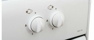
Control
All models are equipped with a simple and convenient control system. It consists of two switches. The first regulates the gas supply, and the second is responsible for the amount of water entering the heat exchanger. There is also a technique with a third switch for the “Winter/Summer” function. The first program uses all burner sections. The “Summer” program, on the contrary, disables some sections - plus savings.
Model overview
Each equipment manufacturer has the most successful models. If we talk about the Vektor brand, we can note several options:
Vector JSD 20
A few years ago, this gas heater won the gratitude of users. It’s not surprising, because the price of the equipment barely reached 4,000 rubles. Also, one cannot help but notice the compact dimensions of the device. Among the equipment, we highlight automatic ignition and a digital display, which greatly simplify the use of the equipment. Another plus for lovers of beauty is that the model is available in three stylish colors: white, gold and silver.
Characteristics:
- Type – flow-through.
- Dimensions – 34x60x18cm.
- Heating is gas.
- Power – 20 kW.
- Capacity – 10 l/min.
- Protection – gas control.
- Features: thermometer, auto-ignition, power indicator, digital display.
Vektor Lux Eco JSD 20-1
The company took a step forward and released a new model - luxury eco. The column is equipped with the same functions as the others, but already has enhanced security. Also, the control has been improved, which allows you to select and adjust temperature modes. As for the design, the heater has an original mirror coating and one of the patterns to choose from. The kit includes the heater itself, faucet, shower, fasteners and instructions.
Characteristics:
- Type – flow-through.
- Dimensions – 64x35x20cm.
- Heating is gas.
- Power – 20 kW.
- Capacity – 10 l/min.
- Protection – gas control.
- Features: “Winter/Summer” mode, auto-ignition, digital display.
Vektor JSD 11- N
The water heater features a high-quality copper heat exchanger - this will extend the “life” of the device. The chimneyless column has a stainless steel burner. All technical details are of high quality. Combined with high performance and low price, the heater is rightfully considered one of the most popular among the model range. The equipment is also equipped with multi-level protection to prevent malfunctions and gas leaks. Unlike its previous “brothers”, the JSD 11-N runs on liquefied gas.
Characteristics:
- Type – flow-through.
- Dimensions – 37x27x14cm.
- Heating is gas.
- Power – 11 kW.
- Capacity – 5 l/min.
- Protection – gas control.
- Features: auto-ignition.