A microwave diode has low electrical resistance, so special care should be taken when handling it. Each diode must be stored in a closed metal socket. It is necessary to ensure that static electricity from the body or devices is not discharged through the diode.
A microwave diode is a semiconductor diode designed to operate in the microwave spectrum.
There are several classes of microwave diodes:
- Mixing;
- Detector;
- Parametric;
- Switchable;
- Restrictive;
- Multiplying;
- Tuning;
- Generator.
Using mixing diodes, you can convert microwave signals into signals with an intermediate frequency. This is possible due to the nonlinear VA characteristics that the high-voltage diode .
The use of switching diodes is relevant for devices that switch microwave signals (protection devices, switching devices, etc.).
The scope of application of a parametric microwave diode is a parametric amplifier, which is a type of resonant regenerative amplifier. The amplifying effect of such a device is associated with pumping the nonlinear capacitance at the diode pn junction, which causes the manifestation of dynamic resistance with a negative value.
A frequency multiplier involves the use of a multiplying diode. The function of microwave diodes of this type is similar to the functional purpose of a multiplying varicap.
And with the help of a tuning diode, you can regulate the resonant frequency in oscillatory systems. In terms of its functional characteristics, it corresponds to a tuning varicap.
Each of the designated classes, in turn, has several subclasses, identified according to the internal structure of the microwave diode and its parameters that are significant for application. It often turns out that diode models from the same subclass are used in units with different functional contents. For example, a microwave multiplier diode can work properly in a mixer.
The most common types of microwave diodes include:
- Avalanche-transmission (Read, Misawa, Tager diodes, etc.);
- PIN diode;
- Gunn diode;
- Point contact diode;
- Schottky or Mott diode.
Diodes of the second type are interesting due to the specifics of their construction: two heavily doped regions with high conductivity (n+, p+) have between them an i-region (active base), which has a low (comparable to the intrinsic conductivity of semiconductor materials) indicator and higher carrier viability charge. This reduces the size of the junction capacitance and helps to increase the operating frequency of the diode.
Detector diodes
One of the most significant types of diodes are microwave detector diodes .
The main purpose of the detector diode is to carry out the process of identifying a low-frequency signal in a modulated voltage, based on which amplitude modulation of high-frequency signals is performed.
The role of the detector diode is predominantly performed by a point-contact diode or Schottky diode. The most significant characteristic of this element is considered to be the steepness of the current-voltage characteristic in the vicinity of the operating point. The value of the detector output voltage should be in direct proportion to how powerful the microwave signal is (the square of the input voltage).
The operation of a microwave detector diode does not primarily imply that the operating point will shift. But when recording a weak signal, it would be appropriate to implement an operating point in the low voltage zone. This is possible for forward-biased microwave diodes.
A certain number of detector diodes have a characteristic close to quadratic. As a result: with their help, you can determine the power of microwave oscillations.
The main special characteristics of detector-type diodes are:
- Current sensitivity;
- Voltage sensitivity;
- Quality coefficient.
When a modulated high-frequency signal is applied to a microwave diode, current flows through the diode with its positive side. If we determine how the indicator of the increment of the current rectified by the diode relates to the microwave power that was the condition for the resulting increment, then the result obtained will be an indicator of current sensitivity. This value is determined if the load is specified and the operating mode has already been established.
The voltage sensitivity value of a microwave detector diode is calculated in a similar way. Only instead of the current increment value, voltage increment data is used. Often this characteristic is determined only for those diodes that are used to detect pulse-type signals. It must be remembered that as the temperature increases, the level of sensitivity tends to decrease.
There is another significant parameter for detector diodes - tangential sensitivity. The main meaning of this criterion is to determine the lowest limit of the signal perceived by the detector.
The qualitative coefficient of the detector diode allows you to immediately evaluate all its basic parameters for efficiency. However, this indicator is calculated using a rather complex formula.
How to discharge a capacitor in a microwave
You can discharge it in the following ways:
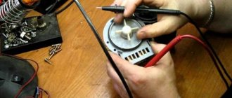
Having disconnected from the power supply, the capacitor is discharged by carefully closing its terminals with a screwdriver. A good discharge indicates its good condition. This method of discharge is the most common, although some consider it dangerous and can cause harm and destroy the device.
Discharging a capacitor with screwdrivers
The high voltage capacitor has an integrated resistor. It works to discharge the part. The device is located under high voltage (2 kV), and therefore there is a need to discharge it mainly to the housing. It is better to discharge parts with a capacity of more than 100 uF and a voltage of 63V through a resistor of 5-20 kiloOhms and 1 - 2 W. For this purpose, the ends of the resistor are combined with the terminals of the device for a certain number of seconds to remove the charge. This is necessary to prevent the occurrence of a strong spark. Therefore, you need to worry about personal safety.
Specifics of the design of high-voltage diodes
By its design, a microwave oven diode consists of a large number of series connections, ultimately forming a single form. This element contains rectifier diodes. Technologically, they are manufactured in exactly the same way; moreover, they are housed in a common body. Assembling a high-voltage diode does not imply the use of capacitors and resistors that could equalize the voltage.
As a result: a diode of this type is characterized by a nonlinear current-voltage characteristic. Therefore, the resistance data for high-voltage diodes directly depends on the voltage value that was applied.
This nature of the assembly makes analyzing the performance of a microwave diode quite difficult.
Remember! Checking a microwave diode using a tester is not feasible. The tester will not demonstrate any accurate readings or data on forward and reverse resistance .
It would be much better to use a multimeter. In this case, it is necessary to take resistance readings for both forward and reverse directions.
Before connecting the multimeter, you must set its mode to R x 1000. As a result, when the “+” terminal of the device is connected to the anode of the microwave diode, the resistance will be measured in the forward direction. The value shown on the display will then be the final value. When the connection is made through the cathode (“-” pin), the value will be infinite.
Causes of failure
All microwave ovens work properly for quite a long period of time. This is due, first of all, to the high reliability of the components. But over time, some of them fail, despite careful operation of the equipment. Therefore, you need to check all the components. The most common malfunctions of the following spare parts are:
- High voltage fuse;
- Capacitor;
- Transformer failure;
- Rectifier diode.
Each of these faults can be corrected independently. As a rule, microwave oven owners have to deal with the diode in case of problems with the operation of the device.
The high-voltage diode may not be immediately noticeable if you are disassembling the microwave for the first time.
How to assess the condition of a microwave diode?
To assess the health of the diode in the microwave oven, you must first perform the following steps:
- Disconnect the device from the electrical network;
- Remove the high-voltage diode from the device (disconnecting it from the electrical circuit);
- Connect the removed diode to the lighting network.
For an incandescent light bulb of this network, a low power is desirable - about 15 V when connected to 220 V. It is important that the light bulb shines half as weakly as possible and clearly flickers.
If this happens when you connect a microwave diode in the forward and reverse directions, then everything is in order. If, after turning the diode over, the nature of the glow changes, then this indicates the presence of a “breakdown” and the need to replace the diode element.
Another way to test microwave diodes will require the use of a charger for mobile devices or tablets, which typically have a voltage of 5 V. In addition, you will need a tseshka.
After everything you need is prepared, you can start checking:
- The microwave diode removed from the device is connected to the circuit;
- During the measurements, the circuit switches to 10 V;
- The received data is analyzed.
If the diode is working properly, then the instrument gauge will stop at 0.25 V (for the forward direction), or will not give any readings at all (for the reverse direction).
In case of malfunctions or “breakdowns”, readings will be absent for both directions.
If problems have been identified in the operation of the microwave diode, it must be replaced.
Device structure
Whatever the cost of the furnace, in any case there will come a time when it will not turn on. And since it will not be possible to avoid breakdown, you should learn how to diagnose the device. Signs of microwave failure will not always be obvious. Quite often, the product simply stops heating food without any sparks or smoke. If this is the situation, it is very likely to repair the stove with your own hands. It is necessary to check the serviceability of all components.
Components:
- Capacitor;
- High voltage diode;
- High voltage transformer;
- Element cooling fan;
- Magnetron;
- Temperature fuse;
- Motor that rotates the bowl;
- Filter;
- Switches.
Microwave device diagram
Troubleshooting
To find out why the oven is not working, you need to unplug it and remove the lid.
- The inside is carefully inspected for melting, burning, or unsoldered wires. The condition of the high-voltage fuse is visible to the naked eye. The fuse with the broken thread is replaced with a intact one, and if during testing of the stove it blows again, the search continues.
- For further diagnostics, you will need a multimeter or tester. The test begins with a printed circuit board on which the magnetron power supply circuit is assembled, consisting of resistors, diodes, capacitors, and varistors. Parts can be called locally, without soldering.
- After that, the thermal fuse is checked with a tester. With normal contacts, the resistance is zero.
- Testing a high-voltage capacitor with a multimeter is only possible for breakdown. If the device shows a short circuit, the part is replaced. Since some types of capacitors have built-in resistors for discharging, a working capacitor will show a resistance of 1 MOhm, instead of infinity.
- The tester is not suitable for testing a high-voltage diode because it has a small resistance measurement range. To correctly assess the condition of the diode, you will need a megohmmeter with a scale of up to 200 MOhm. But it is unlikely to be found in a home workshop. Therefore, a diagnostic method is used using a two-wire home electrical network with mandatory compliance with safety rules. One terminal of the diode is connected to the network wire. A multimeter is connected between the second and the other conductor of the network to measure DC voltage in the range up to 250 V. If the diode is intact, the device will show the presence of rectified voltage. In the event of a breakdown or break, the arrow will remain at zero. Any high-voltage diode with an operating voltage of 5 kV and a current of 0.7 A is suitable for replacement.
- Checking the magnetron begins with testing the filament. To do this, the resistance between its terminals is measured, which for a working filament is several ohms. If the tester shows infinity, this does not mean that the thread is burned out. To be completely sure, after removing the cover, the integrity of the connections of the chokes with the magnetron terminals is checked. Some craftsmen recommend removing the throttles. Under no circumstances should this be done, as the operating mode of the transformer is disrupted, which could result in a fire. After measuring the resistance between the terminals and the housing, you can judge the condition of the feed-through capacitors. At infinity - everything is fine, at zero - they are broken, and if there is resistance - with current leakage. Faulty capacitors are cut off with wire cutters and new ones with a capacity of at least 2000 pF are soldered in their place.
- If all the elements are intact, but the magnetron radiation is not enough to fully heat the food, it means that the cathode has lost emission. This problem can only be corrected by replacement. When replacing capacitors, you cannot use conventional solder; refractory grades or a compact resistance welding machine are required.
The video shows a story for dummies on how to check a magnetron, everything is very clear:
Why does the microwave break?
Despite the fact that users strictly follow the conditions of use, microwave ovens will still break down, and the most common causes of breakdowns are the following:
- Fuse blown.
- Capacitor failure.
- Failure of the high-voltage rectifier diode.
Moreover, all these reasons can, with some desire and skill, be eliminated independently. At the same time, a breakdown of the diode is the most common cause of a malfunction, so it is worth studying the resolution of this particular breakdown.
Magnetron replacement
Since magnetron repair is not carried out even in well-equipped workshops, you will have to purchase a new one. Before removing the magnetron from the microwave, you need to mark the connector contacts so as not to confuse them when installing a new part. If the leads are connected incorrectly, the magnetron will not work.
You can do the replacement yourself if you have at least once used a screwdriver for its intended purpose and rang a couple of diodes. This does not require special skills or knowledge of how a magnetron works. If it is impossible to find a specific magnetron for a microwave, you will have to use a suitable analogue.
Its power must be equal to or greater than that of the original, and the fastening and location of the connector must be the same. The design of the magnetron is the same among manufacturers, but the design may differ, so you need to ensure that the fit of the analogue to the waveguide is tight. If the heat-conducting paste on the thermal fuse is dry, replace it with fresh one.
When purchasing a new magnetron, it is necessary that the power matches, the contacts and mounting holes match. If at least one of the conditions does not match, you have purchased a part that is not suitable for you.
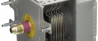
How does a magnetron work?
What a microwave can do. What is a magnetron and microwave energy of a magnetron? A magnetron is a vacuum tube that performs the functions of a diode and consists of several parts:
- A cylindrical copper anode divided into 10 parts.
- In the center there is a cathode with a built-in filament. Its task is to create a flow of electrons.
- At the ends there are ring magnets necessary to create a magnetic field, due to which microwave radiation is created.
- The radiation is captured by a wire loop connected to the cathode and removed from the magnetron using a radiating antenna, directed along a waveguide into the chamber.
During operation, the magnetron gets very hot, so its body is equipped with a plate radiator blown by a fan. To protect against overheating, a thermal fuse is included in the power circuit.
How a magnetron works, diagram.
Installation and connection of a new magnetron
If the part cannot be repaired, the magnetron will have to be replaced. This applies to expensive models, in which case the costs are justified. The best option would be to visit a service center, but you can replace it yourself. Make sure that the used part and the new one match in power and hole location.
Connecting a new magnetron to a microwave oven is not difficult; it only has two contacts. All designations can be found in the diagram. Pay attention to these points:
- the length of the new part should be the same as the old one;
- the antenna diameter in both devices must be the same;
- a tight connection to the waveguide is required.
Contacting the service center in case of problems should be a priority. If the equipment is no longer under warranty, self-inspection and repair will save on the work of specialists.
Useful tips
The following simple recommendations will help extend the life of the magnetron:
- If something crackles and sparks in the microwave when you turn it on, you need to stop using the oven and find out the reason. Fixing the problem will cost less than buying a new part. In this case, the culprit is usually a burnt-out cap, which causes the microwave oven to spark.
- It is necessary to constantly monitor the condition of the mica pad, which protects the output of the waveguide into the chamber from the ingress of fat and food crumbs. If the cap is faulty, the mica may become burnt, which leads to failure of the magnetron. The pad should be kept clean, as any fat that gets on it becomes charred under the influence of temperature and becomes electrically conductive. Interacting with radiation, it causes sparking in the chamber.
- If the voltage is unstable, it is better to connect the microwave through a stabilizer, since even a slight drop negatively affects the operation of the oven. The power drops and wear of the magnetron cathode accelerates. For example, at a network voltage of 200 V, the power is halved.
- A microwave has many uses, so if it malfunctions, the usual order of things is disrupted. The cause of the breakdown is not necessarily the magnetron or its power supply circuit. First, you should check the voltage level at the place where the furnace is connected to the network and the condition of the mica plate.
Determination of capacitor operating voltage
Strictly speaking, if there is no marking on the capacitor and the circuit in which it was installed is not known, then it is IMPOSSIBLE to find out its operating voltage using non-destructive methods.
However, having some experience, you can very roughly estimate the operating voltage based on the dimensions of the capacitor. Naturally, the larger the size of the capacitor and the smaller its capacity, the higher the voltage it is designed for.
Method No. 1: determining operating voltage through breakdown voltage
If there are several identical capacitors and you don’t mind sacrificing one of them, then you can determine the breakdown voltage, which is usually 2-3 times higher than the operating voltage.
The breakdown voltage of a capacitor is measured as follows. The capacitor is connected through a current-limiting resistor to an adjustable voltage source capable of delivering obviously more than the breakdown voltage. The voltage across the capacitor is controlled by a voltmeter.
Then the voltage is gradually increased until breakdown occurs (the moment when the voltage across the capacitor suddenly drops to zero).
The operating voltage can be taken to be 2-3 times less than the breakdown voltage. But this is... You can have your own opinion on this matter.
Attention! Be sure to follow all safety precautions! When checking a capacitor for breakdown, it is necessary to use a protected stand, as well as personal eye protection.
The energy of a charged capacitor is enough to cause a small nuclear explosion right on your desktop. Here you can see how it happens:
And some types of ceramic capacitors, during an electrical breakdown, can shatter into very small but hard fragments that can easily pierce the skin (not to mention the eyes).
Method No. 2: finding the operating voltage of the capacitor through the leakage current
This method of finding out the operating voltage of a capacitor is suitable for aluminum electrolytic capacitors (polar and non-polar). And the majority of such capacitors.
The point is to catch the moment at which its leakage current begins to increase nonlinearly. To do this, we put together the simplest diagram:
and measure the leakage current at various values of the applied voltage (from 5 volts onwards). The voltage should be increased gradually, in equal portions, recording the readings of the voltmeter and microammeter in the table.
I ended up with a sign like this (my instincts told me that this was a fairly high-voltage capacitor, so I immediately started adding 10V at a time):
| Capacitor voltage, V | Leakage current, µA | Current increase, µA |
| 10 | 1.1 | 1.1 |
| 20 | 2.2 | 1.1 |
| 30 | 3.3 | 1.1 |
| 40 | 4.5 | 1.2 |
| 50 | 5.8 | 1.3 |
| 60 | 7.2 | 1.4 |
| 70 | 8.9 | 1.7 |
| 80 | 11.0 | 2.1 |
| 90 | 13.4 | 2.4 |
| 100 | 16.0 | 2.6 |
As soon as it becomes noticeable that the same increase in voltage each time leads to a disproportionately larger increase in the leakage current, the experiment should be stopped, since we are not faced with the task of bringing the capacitor to an electrical breakdown.
If you build a graph from the obtained values, it will look like this:
It can be seen that starting from 50-60 volts, the graph of the leakage current versus voltage becomes clearly nonlinear. And if we take into account the standard range of voltages:
| Standard range of rated operating voltages of capacitors, V | |||||||||||||||||||
| 6.3 | 10 | 16 | 20 | 25 | 32 | 40 | 50 | 63 | 80 | 100 | 125 | 160 | 200 | 250 | 315 | 350 | 400 | 450 | 500 |
then we can assume that for a given capacitor the operating voltage is either 50 or 63 V.
I agree that the method is quite labor-intensive, but not mentioning it would be a mistake.
Whirlpool Microwave Error Codes
| ERR0 | The temperature sensor in the convection system is not connected or short-circuited |
| ERR1 | The magnetron relay is faulty or the wires connecting to it are mixed up |
| ERR2 | Problem with the control board (alternatively one of the buttons is pressed for more than one minute) |
| ERR3 | Temperature sensor error |
| ERR4 | Magnetron temperature sensor error |
| ERR5 | Switching power supply error (power board problem) |
| ERR6 | Load cell calibration failed |
| ERR7 | Moisture sensor error |
| ERR8 | microcontroller error |
| ERR9 | Parameters were not set on the control panel before starting |
| ERRB | There is no signal from the weight sensor or it is not working correctly |
| ERRC | Temperature sensor faulty |
| ERRD | Magnetron overheating protection has tripped |
Magnetron repair
Some hardware components cannot be restored. If the magnetron burns out in the microwave, it will have to be replaced. This component cannot be repaired. The cost of original spare parts for a microwave oven is unusually high. Sometimes it is more profitable to buy new equipment. Therefore, it is extremely important to thoroughly check the magnetron with a tester by measuring the voltage.
Next, we’ll look at how to test a magnetron in a microwave using special measuring instruments. We will provide detailed step-by-step instructions. It is possible that only individual elements of the component are damaged, which makes it possible to carry out repairs without major capital investments.
Anyone who has at least a little knowledge of radio electronics and also has access to a regular tester and megger can handle hardware repairs. If you doubt your abilities, then it is better to seek help from a service center staffed by experienced professionals.
Control unit diagnostics
Microwave oven testing will vary depending on the design of the device. It is customary to distinguish several main types of control units:
The magnetron for a microwave oven is checked with a multimeter. Diagnostics of the control unit is carried out in a similar way. Using this tool, make sure that voltage is supplied to the transformer. If you turn on the timer, having previously selected the operating mode, but there is no voltage, this indicates a failure of the control unit.
The easiest way to repair models is those equipped with a mechanical timer and manual operating mode controls. Start with a visual inspection, and then use a tester to measure the current level at the switch contacts. Such diagnostics allows you to determine: burnt contacts, failed parts, oxidized cables. Replace defective parts.
A microwave with an electronic control unit is more difficult to repair. Perform an initial inspection using the display. If a malfunction occurs, the display will show incorrect information. If the screen does not light up at all, then be sure to make sure that the built-in fuse is intact.
The good thing about the electronic control unit is that each user can start the automatic diagnostic process. Check the detected error code with the values indicated in the special table. This is enough to obtain the necessary information. No multimeter connection required.
The control unit is a radio-electronic module with a rather complex structure. To restore the functionality of this unit, special measuring instruments will be required. If you do not have access to them, contact an authorized service center in Moscow or any other city.
Checking the radio wave emission system
Incorrect operation of hardware components, including the control unit, as well as the magnetron for the microwave oven, indicates the need to check the condition of the elements of the microwave radiation system. It includes a high-voltage transformer as well as voltage shift circuit components. Modern furnaces are equipped with high-voltage MOT transformers. Their design includes three levels of winding:
- primary – 220 V;
- step down – 3 V;
- boost - 2 kV.
To determine a burnt element, you need to sequentially check each winding with a tester. The lowest level of resistance is precisely the step-down winding, which provides heat to the magnetron for the microwave oven. The highest resistance is the high-voltage winding. If a breakdown of the microwave oven is detected, and the user has determined that one or more layers of the winding are broken, replace the transformer.
In no case can we exclude an interturn short circuit, which is observed in the high-voltage winding. A sign of this malfunction will be a low temperature level. The noise may increase significantly during operation of the microwave oven. A conventional multimeter cannot measure the voltage at the output terminals of a given winding. Therefore, you will have to use professional measuring tools. If the fears are confirmed and a short circuit is detected, change the transformer.
Be sure to check all the parts that make up the voltage multiplier system. The magnetron for a microwave oven is a key element of this circuit, but it is far from the only one. It also includes capacitors and diodes. The internal resistance level of a high-voltage diode is very high, and its breakdown cannot be measured with a multimeter. Therefore, you will have to use the megger again. If the part is faulty, then install a new diode.
Be sure to check the capacitor for breakdown. A working component will show resistance close to zero. It will increase significantly in just a few seconds. The resistance of faulty capacitors does not change sharply, since there is no contact with the cover.
It is likely that the oven began to heat food noticeably weaker due to the appearance of a leak between the plates. You can also determine the source of the leak using a megger. Faulty radio elements should be replaced.
Magnetron replacement
If the user is sure that the microwave magnetron is broken, replace this element. This procedure is mainly carried out by qualified specialists. However, everything can be done with your own hands. The main thing is to understand a little about radio electronics, and also know how current voltage is measured.
The replacement procedure in a microwave oven requires that the user first purchases a new component. To make your choice successful, you need to follow a few simple recommendations:
- The power level of the magnetron for a microwave oven fully corresponds to that of a broken device. All necessary information is specified in the technical passport.
- The new part has identical mounting holes, and all contacts match.
- The dimensions of the broken component fully correspond to the dimensions of the new spare part.
Installing a new magnetron for a microwave oven is not difficult. However, the user must achieve the tightest possible fit of the component to the waveguide. Don't forget to check the capacitor.