The operating diagram of a conventional compression-type refrigerator is as follows:
- The compressor, driven by the engine, sucks the coolant gas from the evaporator. The coolant is compressed, heated and enters the condenser.
- There it cools to normal temperature and liquefies.
- Next, the coolant enters the evaporator, where it evaporates, cooling the walls of the heat exchanger that cools the chambers.
- From the evaporator, the coolant again enters the compressor.
- The compressor motor is connected to the electrical circuit through a thermostat. After the refrigerator compartment has cooled to the set temperature, it opens the contacts and turns off the motor.
- Over time, the temperature of the compartment rises, the thermostat reconnects the engine through the start relay.
Refrigeration unit operation diagram
Electrical equipment includes:
- compressor electric motor;
- lighting elements;
- heaters in absorption type systems;
- fans for forced air exchange.
The elements of automation systems include:
- Thermoregulation devices in refrigeration compartments. They can be either mechanical or electronic.
- Start-up protection relays. They serve to facilitate the starting of asynchronous electric motors of compressors and their automatic shutdown in case of overload.
- Systems for removing frost from the evaporator surface.
- Integrated automatic control systems that perform all of the above functions plus monitoring the expiration date of stored products and replenishing their stocks using electronic ordering.
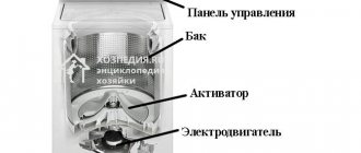
Main components: list, description
Each device participates in the heat exchange process. Continuous and interconnected operation of the devices is required to maintain a constant low temperature in the refrigerator chambers. The devices and what work they do are described below.
Motor-compressor: purpose and features
This is the main node. It circulates the refrigerant in the piping of the heat exchange system. A refrigerator can have one or two compressors - it depends on the consumer properties and purpose.
The purpose of the engine is to drive the compressor. That is, it converts electrical energy into reciprocating movements of the compressor. Modern refrigerators are equipped with piston motor-compressors. That is, the electric motor is located inside the device body. This avoids freon leakage through the shaft seals. As a result, the possibility of breakdown is reduced.
To reduce vibrations from the operation of the compressor, a suspension is used. It is divided into the following types:
- Internal. The engine is suspended on a special damper inside the compressor housing.
- External. The compressor is suspended on a spring.
Internal suspension is most common due to its increased ability to absorb vibrations.
What is a capacitor needed for?
This is a heat exchange device. Heat must be removed from the freon, which condenses, that is, turns into liquid and heats up. In simple models of household refrigerators, the condenser is located on the back wall and is a coil.
If the refrigerator is large or has an industrial purpose, then the radiator serves as a condenser. It is often blown by a fan for more efficient heat transfer. The main thing for a condenser is to cool well. This is the key to long-term operation of the refrigerator.
Evaporator: reverse principle
This is also a heat exchange device. The evaporator only serves to cool the freon. In the device, the refrigerant boils and takes away heat from the environment that needs to be cooled.
Capillary tube: normalization of pressure
Installed between the condenser and evaporator. It is a copper pipe with a length of 1.5 to 3 meters. The cross-sectional diameter of the tube is about 0.7 mm. The purpose of the device is to throttle the liquid refrigerant and lower its pressure to the boiling level before it enters the evaporator.
Filtration of refrigerant by dryer
It is installed at the entrance to the capillary tube. Purpose of the device:
- Prevents clogging of the capillary tube.
- Prevents the tube outlet from freezing.
- Absorption of moisture that accumulates in the refrigerant.
Boiler: compressor amulet
This is the container between the evaporator and the compressor. It is required to ensure that the refrigerant boils and does not enter the compressor in a liquid state. Otherwise, the compressor will experience water hammer and failure. To increase efficiency, the boiler is placed in a place that requires cooling, usually in the freezer.
Description of the cooling process
The devices that make up the refrigerator are known. A diagram of how they interact to cool the internal environment will now be presented.
The operation of a simple refrigerator without additional devices like the NoFrost system is structured as follows:
Using a motor-compressor, refrigerant or freon in a gaseous state is sucked out of the evaporator. The compressor compresses the gas and pushes it through the filter element into the condenser.- As a result of compression, liquid freon heats up. In the condenser it cools to room temperature and turns into a liquid state.
- The refrigerant in its liquid state is under pressure, which is created by the compressor. From the condenser, liquid freon enters the evaporator through a capillary. There the state of aggregation changes back to gaseous. But freon requires heat to transform into gas. It is taken from the walls of the internal cavity of the refrigerator. As a result, the space cools and freon becomes gaseous.
- The process lasts until the temperature preset by the thermostat is reached in the evaporator. Once it is reached, the thermostat will turn off the electrical circuit and the compressor will stop working.
- After some time, the temperature inside the refrigerator will begin to rise as there is no cooling. However, the thermostat will close the contacts and the start relay will turn on the compressor motor. The cycle will repeat again.
As you can see, the refrigerator operation process is based on the transition of the coolant (freon or refrigerant) from liquid to gaseous state. Freon requires heat to turn into steam. It takes away this heat in the internal space of the refrigerator chambers. To automate the process, the refrigerator uses automatic equipment to regulate temperature and turn on/off the electric motor.
Absorption refrigerators, how they work, how they work
Just as in compressor-type refrigerators, the cooling of the internal chambers in devices of this type is not associated with the production of cold, but with the evaporation of the working fluid, which is most often used as ammonia, however, in addition to it, it also contains hydrogen or some other still an inert gas.
Such devices are equipped with an absorber, desorber and reflux condenser. When ammonia is dissolved in water, the entire mixture begins to move. The solution in the absorber, due to its physical properties, moves into the desorber, where it again decomposes into two preliminary components. In the condenser, the working mixture returns to a liquid state, and then again goes to the evaporator. The movement of ammonia is ensured by jet pumps.
Most often, an absorption-type refrigerator is used where a conventional compressor unit cannot be used. In everyday life, such devices are rarely installed due to the toxic substance they contain, which is extremely toxic to humans.
Main types of cooling systems
Based on the principle of operation, the following types of refrigerators are distinguished:
- compression;
- adsorption;
- thermoelectric;
- steam ejector.
In compression units, the movement of refrigerant is carried out by changing the pressure in the system. The pressure of the working fluid is regulated by the compressor. Compressor refrigeration systems are the most common type of refrigeration device.
In absorption units, the movement of the refrigerant occurs due to its heating from the heating system. Ammonia is used as the working mixture. The disadvantage of the system is the high danger and complexity of maintenance. This type of household appliance is obsolete and has now been discontinued.
Did you know that the very first refrigerator was produced by the American company General Electric back in 1911? The device was made of wood. Sulfur dioxide was used as a refrigerant.
The main principle of operation of thermoelectric refrigerators is based on the absorption of heat during the interaction of two conductors during the passage of electric current through them. This principle is known as the Peltier Effect. The advantage of the device is its high reliability and durability. The disadvantage is the high cost of semiconductor systems.
Steam ejector units use water. The role of the propulsion system is performed by the ejector. The working fluid enters the evaporator. Here the liquid boils to form water vapor. When heat is generated, the water temperature drops sharply.
Chilled water is used to cool food. Water vapor is removed by an ejector to the condenser. In the condenser, the water vapor is cooled, turns into condensate and returns to the evaporator. The advantage of such installations is their simplicity of design, safety, and environmental friendliness. The disadvantage of the steam ejector system is the significant consumption of water and electricity for heating it.
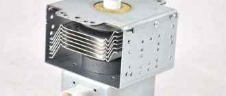
Refrigerator piston compressor design
This device is an electric motor with a vertical shaft; the structure is housed in a sealed metal casing.
External view of a piston compressor with the top casing removed
When the power is turned on by the starting relay, the motor drives the crankshaft, due to which the piston attached to it begins to reciprocate. As a result, freon vapor is pumped out of the evaporative radiator and refrigerant is pumped into the condenser. This process is facilitated by a valve system that opens and closes when pressure changes. The main elements of the piston design are presented below.
Design of a piston compressor in diagrammatic form
Designations:
- The lower part of the metal casing.
- Mounting the stator of an electric motor.
- Motor stator.
- Internal motor housing.
- Cylinder fastening.
- Cylinder cover.
- Valve mounting plate.
- Cylinder body.
- Piston element.
- Shaft with crank pin.
- Backstage.
- Rocker mechanism slider.
- Coil coiled copper tube for refrigerant injection.
- Upper part of the sealed casing.
- Shaft.
- Suspension mount.
- Spring.
- Suspension bracket.
- Bearings mounted on a shaft.
- Electric motor anchor.
Depending on the design of the piston system, these devices are divided into two types:
- Crank-rod. They are used to cool large-volume chambers because they can withstand significant loads.
- Crank and rocker. They are used in two-chamber refrigerators, where two units work together (for the freezer and the main container).
In later models, the piston is driven not by an electric motor, but by a coil. This implementation option is more reliable due to the absence of mechanical transmission, and is economical because it consumes less electricity.
Principle of operation
The principle of operation of the refrigerator is as follows:
- Thermal energy is transferred from the chamber to the environment.
- The cold is concentrated inside the housing.
To remove heat, it is necessary to use a refrigerant called freon. This gaseous composition consists of ethane, chlorine and fluorine. It can pass into liquid and gaseous state. This happens during pressure surges.
The refrigerator compressor draws the refrigerant inside. The system uses an electric motor to drive the rotation of the piston. This mechanism causes compression of the gas.
The process is divided into 2 stages:
- Initially, the piston moves in the return direction, and when it moves, the intake valve opens.
- The piston then moves in the opposite direction, compressing the gaseous substance. The compressed refrigerant acts on the release valve plate, causing a sudden surge in pressure. As a result, the gas heats up to +100 °C, and the valve opens and releases it outside.
The heated substance is sent to the condenser and then transferred to the environment. When heat is transferred, gas condensation starts, and freon acquires the state of a liquid.
Self-defrosting
Models with a self-defrosting function perform the defrosting cycle automatically. There are 2 types of such systems:
- Drip.
- Windy (No frost).
In equipment with a drip function, the evaporator is located at the rear of the device. When the device is operating, frost appears on the back of the wall. During the defrosting process, the frost moves along the gutters to the lower section of the refrigerator. As the compressor heats up, the liquid evaporates.
In models with such a system, air from the evaporator is transferred into the chamber using a fan. Then it flows down the grooves into a special compartment.
The word “no frost” means nothing to beginners. Therefore, when familiarizing yourself with the principle of operation of the refrigerator, it is necessary to clarify how the No frost system works and what it is.
Inverter
Compressor units in inverter refrigerators accumulate and convert direct current into alternating current with a rated voltage of 220 V. The principle of their operation is to smoothly change the speed of the motor shaft.
When the refrigerator starts, the inverter reaches the required number of revolutions to maintain normal temperature conditions under the body. After this, the equipment goes into the waiting stage. As the temperature rises, the sensor is triggered and the rotation speed increases.
Absorption
The specificity of the operation of absorption models comes down to the uninterrupted circulation and evaporation of freon in a liquid state. Its role is played by ammonia, and an aqueous ammonia composition is used as an absorber (absorbent).
The cooling system contains sodium chromate and hydrogen. The first protects the walls from corrosive processes, and the second regulates the pressure in the system.
When the equipment is connected to the power supply, the boiler heats the working composition placed in a special container. After this, the liquefied refrigerant is transferred to the evaporator and combined with hydrogen. Due to the pressure difference between the two compositions, ammonia evaporates.
The cooled substance takes away thermal energy from the outside.
Industrial
Industrial equipment differs from household equipment in terms of power and dimensions of the cooling chambers. The productivity of refrigerators reaches several tens of kW, and the operating temperature range of freezers varies between +5…-50 °C.
Industrial units are used for efficient cooling and deep freezing of food. The chamber volume varies from 5 to 5 thousand tons. The main areas of application are enterprises for the preparation and processing of products.
Diagram and principle of operation of a two-chamber
The operating schemes for obtaining sub-zero temperatures in a two-chamber refrigeration unit and positive temperatures are different.
In such household appliances, there is a heat-insulating partition between the freezer and refrigerator compartments; each compartment has its own evaporator. The unit operates on the following principle: using a compressor, freon is supplied to the freezer (a group of saturated aliphatic fluorinated hydrocarbons, used in refrigeration units). This gas boils and evaporates, entering the air cooler, and its surface temperature decreases.
This process is repeated until the temperature drops below zero. Gas is not directed to the air cooler of the refrigeration chamber, since no cooling occurs in it. However, after the freezer compartment has completely cooled, the refrigerant enters the refrigeration evaporator.
In refrigeration compartments with a small volume, an air cooler is placed, the dimensions are significantly smaller than the evaporator of the freezer. The temperature in the refrigerator compartment is always above 0, and on average 4-6 degrees Celsius.
The photo shows the electrical circuit of a two-chamber refrigerator. Lg, Ariston, Veko, Gorenie, Samsung have such schemes.
Inverter and conventional refrigerators
There are two types of compressors - conventional and inverter. They differ in their internal structure and operating mode. Previously, all refrigerators were equipped with linear ones, but now inverter ones are gaining popularity.
A conventional compressor operates in a start-stop mode. For example, when the temperature in the chamber rises 1 degree above the desired temperature, the compressor turns on and the refrigerator begins to cool. Once the temperature has reached the desired temperature, it turns off.
The inverter compressor runs constantly, but with little power. It maintains the temperature at a given level. At the same time, its total energy consumption is lower than that of a conventional one.
The advantage of a linear compressor is that it does not experience stress when turning on and off. Accordingly, its service life is much longer. But inverter equipment also costs more than conventional equipment.
In this article, we described the principle of operation of the refrigerator and touched on other topics. We hope you found it useful. Don't forget to share the post with your friends!
Scheme of operation of electrical devices
The operating principle of the refrigerator electrical circuit:
- Electric current is supplied from the public network through the following devices:
- Thermostat contacts (assume that they are closed).
- On the defrost button (if available).
- To the thermal protection relay.
- To the start relay coil.
- To the winding of the compressor electric motor.
- At this point the motor is not turning. This means that the electric current flowing through the motor winding exceeds the rated current. The starting relay is designed in such a way that when the nominal voltage is exceeded, its contacts close. As a result, the motor winding is connected. After the engine begins to rotate, the current begins to decrease at the starting relay. Once the rated voltage is reached, the contacts on the starting relay open and the motor operates normally.
- The temperature in the evaporator will drop over time. After reaching a certain value, the thermostat contacts open. As a result, the electric motor stops and the compressor no longer works.
- Since the compressor is no longer running, the temperature in the evaporator begins to gradually increase. After the temperature rises above the set threshold, the thermostat contacts close, after which the cooling cycle is repeated.
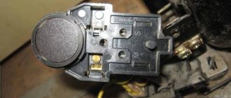
The electrical circuit of the refrigerator also contains a protection relay. It turns off the electric motor if the electric current is supplied in excess. This helps protect both the electric motor winding and the entire home from possible fire due to overload in the electrical network and its impact on the electrical system of the refrigerator.
The design of the protection relay is simple. It consists of a thin metal plate. When the temperature rises, which arises due to the increased resistance of the electric current when it is in excess, the plate bends, resulting in the contacts opening. After the plate cools, the contacts close again.
https://youtube.com/watch?v=IkNikwNRzFo
Schematic diagram of a refrigerator
Just 30 - 40 years ago, household refrigerators had a fairly simple structure: the motor-compressor was started and turned off by 2 - 4 devices, and there was no question of using electronic control boards.
Modern models have many additional options, but the principle of operation remains generally unchanged.
The thermostat is the main and only control element with which the user can configure the operation of an old refrigerator; it is usually located inside the refrigerator compartment. The bellows spring is hidden under the power lever - the rotating handle. It contracts when the chamber is cold, thereby opening the electrical circuit and turning off the compressor.
As soon as the temperature rises, the spring straightens and closes the circuit again. The refrigerator's freezing power indicator knob regulates the permissible temperature range: the maximum at which the compressor starts and the minimum at which cooling stops.
The thermal relay performs a protective function: it controls the temperature of the engine, therefore it is located directly next to it, often combined with the starting relay. If the permissible values are exceeded, and this can be 80 degrees or more, the bimetallic plate in the relay bends and breaks the contact.
The motor will not receive power until it cools down. This protects against both compressor failure due to overheating and a house fire.
The motor-compressor has 2 windings: working and starting. Voltage is supplied to the operating winding directly after all previous relays, but this is not enough to start. When the voltage on the operating winding increases, the starting relay is activated. It gives an impulse to the starting winding, and the rotor begins to rotate. As a result, the piston compresses and pushes freon through the system.
In general, the operating cycle of the refrigerator can be described as follows:
- Connection to the network. The temperature in the chamber is high, the thermostat contacts are closed, the motor starts.
- Freon in the compressor is compressed, its temperature rises.
- The refrigerant is forced into the condenser coil, located behind or in the refrigerator tray. There it cools, gives off heat to the air and turns into a liquid state.
- Through the dryer, freon enters a thin capillary tube.
- Entering the evaporator located inside the refrigerator chamber, the refrigerant expands sharply due to an increase in the diameter of the tubes and the transition to a gaseous state. The resulting gas has a temperature below -15 degrees and absorbs heat from the refrigerator chambers.
- The slightly heated freon enters the compressor, and everything starts all over again.
- After some time, the temperature inside the refrigerator reaches the set values, the thermostat contacts open, the motor and freon movement stop.
- Under the influence of the temperature in the room, from new warm products in the chamber and opening the door, the temperature in the chamber rises, the thermostat closes the contacts and a new cooling cycle begins.
This diagram exactly describes the operation of old single-compartment refrigerators, which have one evaporator.
Typically, the evaporator is the freezer housing at the top of the unit, not isolated from the refrigeration chamber. We will consider the differences in the design of other models below.
Smart refrigerators with electronic control
Classic thermostats, with a mechanical rotary knob and a bellows inside, are becoming less and less common in modern refrigerators. They give way to electronic boards capable of managing an ever-increasing variety of operating modes and additional refrigerator options.
The function of determining temperature instead of a bellows is performed by sensors - thermistors. They are much more accurate and compact, often installed not only in each refrigerator compartment, but also on the evaporator housing, in the ice maker and outside the refrigerator.
Many modern refrigerators have an electric air damper drive, which makes the No Frost system as efficient, convenient and accurate as possible in setting
The control electronics of many refrigerators are made on two boards. One can be called user: it is used to enter settings and display the current state. The second is system, through a microprocessor it controls all devices of the refrigerator to implement a given program.
A separate electronic module allows the use of an inverter motor in refrigerators.
Such motors do not alternate cycles of operation at maximum power and idle time, like conventional ones, but only change the number of revolutions per minute, depending on the required power. As a result, the temperature in the refrigerator chambers is constant, electricity consumption is reduced, and the operating life of the compressor is increased.
The use of electronic control boards incredibly expands the functionality of refrigerators.
Modern models can be equipped with:
- control panel with or without display, with the ability to select and set the operating mode;
- multiple NTC temperature sensors;
- FAN fans;
- additional electric motors M - for example, for crushing ice in an ice generator;
- HEATER heaters for defrosting systems, home bar, etc.;
- VALVE solenoid valves - for example, in a cooler;
- S/W switches for controlling the closing of the door and turning on additional devices;
- Wi-Fi adapter and remote control capability.
The electrical circuits of such devices are also repairable: even in the most complex system, the cause of a malfunction is often a faulty temperature sensor or similar small detail.
Side-by-side refrigerators with touch screen controls, ice maker, built-in cooler and many customization options are controlled by a fairly extensive and complex electronic board
If the refrigerator “glitches” and refuses to correctly execute the specified program, or does not turn on at all, most likely the problem concerns the circuit board or the compressor; it is better to entrust the repair to a specialist.
Compressor problem?
- Remove the compressor and start protection relay.
There will be 3 contacts under it: the starting and working windings and the common one. - On modern (especially imported) compressors, the nameplate or stickers show the location of the contacts in accordance with the windings. If not, arm yourself with a multimeter and measure the resistance
between them. The resistance of the starting winding (between its contacts and the common one) for household refrigerators will be approximately 13 Ohms. Working - 43-45 Ohms. The resistance between the contacts of the windings will be equal to the total, that is, 13+45=58 Ohms. Fluctuations are allowed depending on the power and model of the unit. - We make a simple device that simulates the operation of a start-up relay: we connect 2 two-wire wires to the plug, one of which is opened using a button. We connect the direct wire to the working winding, the open wire to the starting winding, the common wire to the common contact. Press the button and insert the plug into the socket. If the compressor is working properly, it will start. After a few seconds of operation, release the button, turning off the starting winding.
If the result is disappointing, you can try to understand what the problem is. But the value of this knowledge is questionable, because repairing a compressor in most cases costs more than buying a new analogue,
and not every office will undertake such labor-intensive work. But still:
- A problem that you may have noticed while making your “relay”. When trying to measure resistance, did the multimeter show a break? This means the windings are broken, there is no contact. The repair consists of rewinding them, but this is too painstaking work.
- Put the multimeter in ringing mode and check if it penetrates the housing. Bring one probe to the body, touch the other one to the contacts of the windings. If the device shows contact, there is a breakdown, the motor is broken.
- When operating for a long time under heavy load (never fill a freezer full of warm meat!) the compressor can become very hot. In this case, the insulation of the wires in the winding melts, and it begins to work without using all its power. The compressor gets very hot, cannot provide pressure to operate normally, and the thermal protection trips regularly.
- Other, more serious accidents, such as water hammer. You will definitely notice a loud rumble somewhere at the bottom of the refrigerator and, for the future, know that after this, the compressor can simply be taken for scrap.
“How is the start-up relay of a refrigerator replaced? Why does the relay fail? How to replace the start relay yourself? We will tell you about this in more detail"
Household and industrial refrigerators are a rather complex engineering embodiment. They consist of many components and electronic boards. All processes in refrigeration equipment are interconnected and the breakdown of one small spare part can paralyze the operation of the entire device. The same thing can happen due to the failure of the start-up relay. This component is designed to start the compressor in a timely manner. The motor is not able to start working on its own without this small box, which in turn also protects the compressor from overheating and wear. As soon as the motor begins to overheat, the relay opens the electrical circuit. The current does not enter the electrical circuit and the operation stops. This protects such an important unit from premature failure.
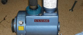
Connecting the refrigerator compressor relay
To connect the refrigerator compressor relay, you need to follow a few simple steps. This uses a windshield washer hose. Finding it won't be difficult. It is available in almost any store that sells spare parts for cars.
Regarding the operation of the device, it is important to monitor the oil level. This will avoid overheating
In this case, the duration of operation of the device should not exceed forty-five minutes. Otherwise, it may quickly fail.
This device is electric. Therefore, when using it, it is necessary to observe safety precautions. Before starting operation, the quality of the wire insulation must be checked. In this case, only special material is used. Hands must be dry when using the device.
Refrigerator without electricity - fact or fiction?
Nigerian resident Mohammed Ba Abba received a patent for a refrigerator without electricity in 2003. The device consists of clay pots of different sizes. The vessels are stacked into each other according to the Russian “matryoshka” principle.
Refrigerator without electricity
The space between the pots is filled with wet sand. A damp cloth is used as a cover. Under the influence of hot air, moisture from the sand evaporates. The evaporation of water leads to a decrease in the temperature inside the vessels. This allows you to store food for a long time in hot climates without using electricity.
Knowledge of the structure and operating principle of the refrigerator will allow you to perform simple repairs of the device yourself. If the system is configured correctly, then the device will work for many years. For more complex malfunctions, you should contact service center specialists.
Ariston refrigerator diagram
Schematic diagram of the refrigerator Hotpoint Ariston MB 2185 NF.019
L – phase, N – neutral, TH1 – refrigerator compartment thermostat, TH2 – freezer compartment thermostat, RH1 – compressor thermal relay, RA1 – compressor start relay, SL1 – refrigerator compartment indicator lamp, SL2 – freezer compartment indicator lamp, IL1 – lamp switch, L1 - refrigeration compartment lighting lamp, TIM - timer, TR - TR thermal relay for evaporator heating element, TF - fuse, CO1 - refrigerator compartment compressor, CO2 - freezer compartment compressor, R1 - evaporator heating element, R2 - drip tray heating element, RA2 - starting compressor relay, RH2 - compressor thermal relay
No Frost system and self-defrosting
The refrigerators described above have a drip defrosting system. This means that the refrigeration chamber is equipped with a “crying” evaporator: when the compressor is idle, the frost on it melts naturally, because the temperature in the chamber is positive.
The resulting water flows through special gutters through a tube into a container located above or near the motor. Later, the running motor becomes very hot and the water evaporates. A freezer with such a system never thaws on its own, and frost forms not only on the walls of the chamber, but also on the food.
No Frost refrigerators do not need to be defrosted; you will not see frost in their chambers, even in the freezer. A characteristic feature of such models is the presence of a fan that distributes cold air from the evaporator among the chambers.
No Frost refrigerators contain standard start-up protection relays, an improved thermal relay, as well as a fan and heating elements for automatic defrosting
The cooling coil itself in such models does not look like the usual solid metal plate, but like a car radiator or the condenser coil on the back of old refrigerators.
In the general operation scheme of the refrigerator, the new elements behave as follows:
- the fan or turbine starts together with the compressor and evenly distributes cold air among the chambers;
- when the thermal relay opens the contacts supplying the engine due to the achievement of the set temperature, the fan is simultaneously turned off;
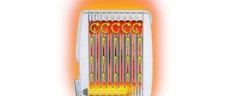
- Once every 8 - 16 hours the thermal relay turns on the heating element. This is an electrical mat or wire that heats the evaporator coil to remove frost from it. Warm air does not enter the refrigerator chambers, since the evaporator is hidden and the fan is turned off;
- when all the frost has thawed, the temperature compensation switch turns off the heating;
- Additionally, the thermostat can control a damper that regulates the supply of cold air into the main chamber through the channels.
Defrosting such refrigerators is similar to a “crying” evaporator in only one way: the resulting water also flows through the channels into a container near the motor.
The evaporator and fan can be hidden in the partition between the chambers, and different numbers of air ducts and movable dampers in them are used to regulate the temperature
The scheme described above is the most primitive. Most modern models are controlled centrally, from an electronic board.
The main disadvantage of No Frost refrigerators is the drying out of food due to constant air circulation. Everything has to be stored in containers with tight lids or wrapped in film.
An original solution to the problem is offered by Electrolux in the Frost Free system. In these units, the freezer operates according to the No Frost system, and a classic, “crying” evaporator is installed in the chamber with a positive temperature. The electrical circuit is generally identical to standard “no frost” systems.
How self-defrost works
There are two types of self-defrosting systems for refrigerators:
- Drip (Direct Cool);
- No Frost.
The drip system only works in the main compartment and cannot be installed in the freezer. The No Frost defrosting system works both in the main chamber and in the freezer.
Drip system (Direct Cool)
In a drip system, the evaporator is mounted into the back wall of the main compartment of the refrigerator and cools it. That, in turn, cools the air in the compartment. With this arrangement, over time, condensation forms on the wall and collects into drops, which freeze and turn into ice.
Periodically, the system turns off and the ice on the wall begins to melt. Drops of water flow down and fall into a special chute. They pass through it into the pan, where they evaporate due to the heat generated by the compressor during operation.