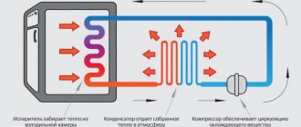
Any modern electromechanical equipment is equipped with special devices that regulate its operation and protect it from overloads. In refrigerators of any manufacturer, such a device is a start-up relay. Thermal relays play an important role in refrigeration units. Its malfunction can lead to incorrect cooling mode and loss of equipment functionality.
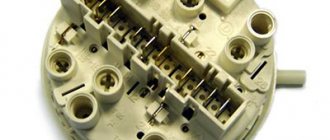
Start-up relay - top view
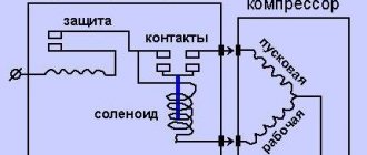
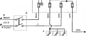
Start relay connection diagram
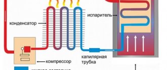
This device is necessary to start a single-phase asynchronous compressor motor. The motor stator includes two windings - starting and working. The first serves only to create starting torque and start the compressor. The second winding is needed to maintain the rotor in working condition by continuously supplying alternating current to it.
Important! To regulate the process of supplying and turning off power to the starting and operating windings of the electric motor, as well as for the overload protection function, a starting protection relay is provided.
Inductive closing mechanism
The relay connection diagram is not complicated. Conditionally “zero” and “phase” power is supplied to the input of the device, and at the output “phase” is divided into two lines. The first line is connected to the working winding of the electric motor, and the second line is connected to the starting winding through the starting contact.
In relays of old and modern refrigerators, current is supplied to the working winding through a spring with high resistance, and then through a connection with a bimetallic jumper. With a strong increase in current in the circuit (motor jamming, short circuit between turns, and other breakdowns), the spring in contact with the jumper heats up, which changes its shape under the influence of temperature, thereby opening the contact and turning off the compressor.
Inductive circuit circuit
In this circuit, a coil (K1) is used to start the electric motor, which is connected in series with the working winding. Applying voltage while the motor rotor is stationary provokes an increase in current in the coil with the formation of a magnetic field that attracts a movable core that closes the starting contact. After the rotor picks up speed, the current in the circuit decreases, the magnetic field in the solenoid decreases, and the starting contact opens by gravity or a compensating spring.
PTC switching mechanism
Modern household refrigerators use a start-up relay with a built-in posistor (a resistor that increases resistance as the temperature rises). The circuit of this device (Fig. 2) is similar to an induction relay, only instead of a coil, a posistor connected to the starting circuit is used to close and open the starting contact.
When power is supplied to the compressor, the temperature of the resistor is low and it passes current to the starting winding. Since the resistor initially has resistance, it heats up and opens the circuit of the starting winding of the engine. The cycle is repeated after the thermostat is triggered and the refrigerator is then turned on again.
PTC switching mechanism
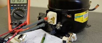
Continuity testing of air conditioning compressors
The most common type of compressor in air conditioners is single-phase compressors with a starting winding.
To gain access to the compressor contacts, it is necessary to disassemble the air conditioner so that there is access to the compressor. Usually the contacts are protected by a cover that is screwed in place; you can find it by the wires that go to the compressor. After removing the cover, you will see three contact pins on which terminals with wires are attached.
It is necessary to remove the wires and measure the resistance between the terminals with a multimeter. We set the device switch to the resistance measurement function (indicated by the letter Ω). If the multimeter shows an infinitely large resistance between terminal C and the others, then this means a break; in the case of built-in protection, you need to make sure that the compressor is not overheated and the protection has not tripped; otherwise, and if the external protection is faulty, the compressor is faulty. If the resistance approaches zero, this means a short circuit and the compressor is also faulty.
The exact value of the resistance depends on the power of the compressor, the accuracy of your device and can range from approximately 1-20 ohms.
As can be seen from the diagram, the resistance between terminals M and S must be equal to the sum of the resistances between terminals S and C and between M and C.
As a rule, the operating winding (MC) is more powerful, so its resistance is lower than that of the starting winding (SC).
Each compressor has thermal protection, but it can be built-in as in the diagram, or located under the cover, next to the compressor terminals.
If it is not built-in, the so-called “tablet”, then it can be ringed separately and replaced in case of malfunction (it must be closed in the normal state, opens when a certain temperature is reached 90-120 ° C).
I’ll immediately make a reservation that in this way we will not be able to determine short-circuited turns; there are other devices for this (but they also do not detect short-circuited turns stably enough).
Thermal relay circuit
The thermostat in a refrigeration unit plays the role of a device that maintains operation at a given temperature by periodically turning the compressor on and off. At the present stage, 2 types of thermal relays are used:
- Mechanical devices are used in old refrigerators, as well as in such modern manufacturers as Indesit, Stinol, Atlant.
Mechanical thermostat diagram
This device is of a manometric type. The bellows and its tube (sealed corrugated metal container) are filled with freon or chlormethyl, which is in the form of steam. The pressure of the working medium changes directly proportionally with temperature changes. At the end of the tube, freon is in a liquid state and is pressed against the evaporator.
As the temperature increases, the pressure of the bellows on the spring increases, the lever is activated, and the contact closes. When the temperature decreases, the opposite happens. The contact opening mode depends on the spring force, which is adjusted by the control knob.
- Electronic thermostats are used in refrigerators from manufacturers such as Samsung, Beko, LG.
Mechanical thermostats rely on the temperature in the evaporator in their operation, while electronic thermostats rely on the air temperature in the chamber. The positive aspect of electronic models is the ability to display temperature (that is, a person can visually assess the operation of the thermostat) and less error.
Electronic thermostat circuit
The temperature controller in this circuit is the LM335 temperature sensor. The device is a zener diode, sensitive to temperature changes. The climate in the refrigerator chamber is regulated by variable resistance R4. When the air temperature rises, a signal appears at the output of the TLC271 comparator, opening the KT3102 transistor, which starts the refrigerator. Accordingly, when the temperature drops, zero appears at the output of the comparator and the compressor turns off.
How it works and where it is located
The refrigerator thermostat device resembles a relay, one end of which is equipped with a sealed tube filled with refrigerant. On the other side there are contacts, the disconnection of which sends a signal to the compressor. The freon tube is attached to the evaporator. The operating principles of the thermostat include the following:
- The refrigerant circulating in the tube reacts quickly to changes in temperature. If it increases or decreases, the pressure in the capillary changes.
- When the contacts are closed or disconnected, the spring is activated. The part is used to control the temperature level in the chamber. The spring is connected to the regulator. Turning the knob changes the degree of compression of the spring. Because of this, the intensity of the force applied to displace the contacts is reduced or increased.
- When the contact position changes, the relay starts or stops the compressor. This is how the temperature in the freezer and refrigerator compartments is regulated.
In electronically controlled devices, the mechanism of action of the relay that operates in the refrigerator will be somewhat different. The required temperature indicator is achieved by recording the actual indicators with a capillary tube. An electronic module is needed to receive signals from several sensors. It is almost impossible to repair such a thermostat with your own hands.
Inside
This arrangement of the thermostat is typical of older models of refrigeration units. This part is located inside the camera, it is protected by a plastic case.
Outside
In this case, the thermostat is found near the temperature mode selection knob. To remove the part, you must remove the fasteners and remove the regulator.
Checking the refrigerator relay for functionality
If the refrigeration unit does not turn on or does not turn on regularly, then most likely the problem is with the start relay. The reason for its malfunction may be:
- Oxidation or burnt contacts.
- Mechanical damage.
- Overheating of the posistor element.
- Failure to secure the relay, leading to its incorrect positioning.
- Spiral burnout.
- Core jamming.
There is no need to rush to buy a new refrigerator relay, it is better to find out how to test it and try to do it.
In the induction mechanism, the solenoid is pulled out, the contacts are checked, and if oxidized, they are cleaned with sandpaper. The core may be broken, then it needs to be replaced. Wipe contacting surfaces with alcohol. Check the integrity of all elements. It must be remembered that relays of this type are installed strictly in a certain direction, indicated by the arrow. After the above steps, connect the relay to the compressor and turn on the refrigerator. If the engine does not start, then most likely the compressor is broken.
Checking RTP-1 and RTK-X devices
To check, place the relay in the correct position (arrow up) and ring contacts 1 and 3 with a multimeter.
RTK-X device diagram
If the contacts ring, then the relay is working properly. In these models, a visual inspection is advisable, since a short circuit can occur through the contact holder plate.
Checking DXR and LS-08B devices
The DHR needs to be placed with the terminal strip facing up and checked with a multimeter for continuity between 1 and 3 or 1 and 4.
Place LS-08B with the inside facing up, ring between 2 and all terminals or between 3 and all terminals. Where the contacts do not ring through, look for the fault there.
Signs of breakdown
Indicators of a malfunction of the thermostat may include an increase in the operating time of the compressor, a decrease in the temperature in the main chamber, and spontaneous shutdown of the device.
The refrigerator does not turn off on its own
To understand that the temperature controller is faulty, you need to perform the following steps:
- disconnect the refrigerator from the power source by unplugging the plug from the socket;
- remove food and shelves, completely defrost the chambers;
- move the relay knob to the maximum position or switch the refrigerator to intensive freezing mode;
- put an outdoor thermometer in the main chamber that can record negative temperatures;
- turn on the device and wait 2-3 hours;
- remove the thermometer and evaluate the readings (the thermometer must show at least 6°C; if the value differs from normal, the thermostat needs to be repaired).
Disconnected and working
The reason may lie in the failure of the thermostat, compressor or start relay. To make sure that the thermostat requires repair, you need to perform the following steps:
- disconnect the refrigeration unit from the power supply;
- find the thermal relay and remove it from the housing;
- inspect the part for defects.
The thermostat has several different colored cables. The yellow-green wire is pulled to the side to prevent accidental damage. The remaining cables are twisted and connected to each other. If, after returning the part to its original position and turning on the refrigerator, the engine starts, a breakdown has occurred in the temperature controller.
Snow coat in the refrigerator compartment
There may be several reasons for the appearance of a thick layer of ice on the back wall of the refrigerator compartment. System testing is carried out as follows:
- First you need to measure the temperature of the inside of the refrigerator using a thermometer. If this indicator is below normal, turn the mode selection knob until the compressor turns off. If the device reacts, then the relay is working correctly.
- The refrigerator is emptied of food and turned on for several hours. At this time, it is necessary to record the duration of the periods of operation and rest of the compressor. About 45 minutes should pass between motor operation cycles.
- If the duration of the compressor rest period differs slightly from normal, turn the knob to select a lower temperature. If the refrigerator starts to run continuously, the thermostat needs to be replaced.
Checking the thermostat
If your refrigerator does not turn off for a long time, constantly works or does not turn on at all, then the thermostat may be to blame. The culprit must be dismantled, and a jumper must be placed on the remaining contacts. If the refrigerator turns on, check the thermostat itself. It is placed in a container with cold water, and the outputs are tested with a tester or the resistance at the output is measured.
Dialing contacts with a tester
If there is no sound signal or if resistance is present, the thermal relay is faulty and must be replaced.