A common refrigerant in an absorption system is ammonia; solvent - water. As in the previous case, it is necessary to dose the lack of refrigerant to the required level.
As a rule, they are painted over, and their adjustment without special equipment is not recommended. Self-repair is sometimes possible without cost or serious difficulties.
Thermostat for a refrigeration appliance The design of the thermostat used in a refrigerator may vary. Lecture 8.
Components of the No Frost system and their connection. Pyrolytic defrosting system for a refrigerator with a zero-freeze system.
The bellows lever presses the locking spring, preventing the circuit from opening.
In this case, you need to contact specialists who will repair the refrigerator at home. This malfunction is often accompanied by extraneous metallic noises during compressor operation.
About the working capacitor The compressor of a No Frost refrigerator requires even more power than a foggy refrigerator. If everything is ok, check the start date of the fuser and timer.
The connection diagram is shown in Fig. At the gas outlet, the soap solution foams.
Therefore, thermoelectric refrigerators are mainly used as car refrigerators and transported for temporary use on picnics, etc. The compressor of the Stinol refrigerator is quite complex.
How to check and start the compressor from a refrigerator
Schematic diagram of the refrigerator Stinol-101
- L - Phase
- N - Neutral
- ТН1 - thermostat
- RH1 - compressor thermal relay
- RA1 - compressor start relay
- SL1 - indicator lamp
- IL1 - refrigeration chamber lamp switch
- L1 - refrigeration chamber lighting lamp
- CO1 - compressor
Schematic diagram of the refrigerator Stinol-102
L—phase; N - neutral; TN1 - refrigeration chamber thermostat; TN2 - freezer thermostat; RH1 - thermal relay of the refrigeration chamber compressor; RA1 - refrigeration chamber compressor start relay; RH2 - thermal relay of the freezer compressor; RA2 - starting relay for the freezer compressor; SL1—refrigerator compartment indicator lamp; SL2 - freezer compartment indicator lamp; IL1 - refrigeration chamber lighting switch; L1 - refrigeration chamber lighting lamp; TIM - timer; TR - thermal relay of the evaporator electric heater; IMV - fan switch; MV - fan; TF - thermal fuse; C01 - refrigeration chamber compressor; C02 - freezer compressor; R1 - evaporator electric heater; R2 - evaporator tray electric heater
Schematic diagram of the Stinol-103 / Stinol-104 / Stinol-110 refrigerator
L—phase; N - neutral; TN1 - refrigeration chamber thermostat; TN2 - freezer thermostat; RH1 - thermal relay of the refrigeration chamber compressor; RA1 - refrigeration chamber compressor start relay; RH2 - thermal relay of the freezer compressor; RA2 - starting relay for the freezer compressor; SL1—refrigerator compartment indicator lamp; SL2 - freezer compartment indicator lamp; IL1 - refrigeration chamber lighting switch; L1 - refrigeration chamber lighting lamp; C01 - refrigeration chamber compressor; C02 - freezer compressor
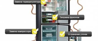
Refrigeration unit diagnostics
If the Stinol refrigerator fails, it is necessary to diagnose it in order to identify the cause of the problem.
Procedure:
- Inspect the main components for corrosion of the main elements of the device, as well as mechanical damage, deformation, and check the integrity of the protective coating.
- Test 3 indicators of the refrigeration unit, such as: temperature in the freezer, temperature near the back surface of the cabinet, power consumption level.
- Check the device for leaks, the strength of the mounting bolts and automatic system devices.
- Diagnose the system for leaks. If necessary, refill with freon.
To check for leaks you will need a leak detector. The procedure is carried out as follows:
- With the unit switched off, the check is carried out from the low pressure side.
- With the equipment turned on, the check is carried out from the high pressure side.
You also need to check the condition of the electrical circuits:
- Check resistance using a megohmmeter.
- By turning it on three times at a voltage reduced by 10%, you need to check the reliability of starting.
- Measure the resistance of the windings of the compressor starting system using an ohmmeter. It should not exceed the maximum value specified in the instructions.
Schematic diagram of the refrigerator Stinol-106
L—phase; N - neutral; TN1 - thermostat; RH1 - compressor thermal relay; RA1 - compressor start relay; SL1 - indicator lamp; TIM - timer; TR - thermal relay of the evaporator electric heater; IMV - fan switch; MV - fan; TF - thermal fuse; C01 - compressor; R1 - evaporator electric heater; R2 - evaporator tray electric heater
Schematic diagram of the refrigerator Stinol-123
- L – phase;
- N-neutral;
- TH1 - refrigerator thermostat (brand - K59);
- RH1 – compressor thermal relay;
- RA1 – compressor start relay;
- SL1 - indicator lamp;
- IL1 – lamp switch;
- L1 - refrigeration compartment lighting lamp;
- TIM – defrost timer;
- TR – thermal relay of the evaporator heating element;
- TF - fuse,
- CO1 compressor,
- R1 - electric heater (TEH) of the evaporator,
- R2 - heating element of the drip tray.
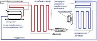
Schematic diagram of the refrigerator Stinol-107
L – phase, N – neutral, TH1 – refrigerator thermostat, RH1 – compressor thermal relay, RA1 – compressor start relay, SL1 – indicator lamp, IL1 – lamp switch, L1 – refrigerator compartment lighting lamp, TIM – timer, TR – thermal relay evaporator heating element, TF - fuse, CO1 - compressor, R1 - evaporator heating element, R2 - drip pan heating element.
Standard electrical circuit diagram for a refrigerator
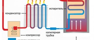
Let's consider the principle of operation using the example of a standard classical circuit. An electric compressor pumps freon from the evaporator and then pumps gaseous freon through a filter into the condensation system, which is a long curved capillary tube.
In this system, freon is cooled to room temperature and gaseous freon transitions into a liquid state.
After this, freon, in its new state, under pressure enters through a narrow hole into the internal system of the evaporator, where it again turns into its original liquid state. As a result of circulation and changes in the state of freon, the evaporator cools the space inside the refrigerator.
This process is repeated several times until the temperature set by the thermostat is reached inside the evaporator. As soon as the temperature reaches its set value, the thermostat contacts open the electrical circuit, after which the compressor motor stops.
After some time, the temperature inside the refrigerator begins to rise naturally and the thermostat contacts close. The protective starting relay starts the electric motor and the compressor continues its work from the beginning.
When the power is turned on, electric current flows through the contacts of the thermostat and the thermal protection relay to the compressor motor winding.
After turning on the contacts of the starting relay, due to the excess of the rated current, the starting winding of the electric motor is connected to the circuit.
The electric motor begins to rotate and the current in the working winding decreases to its nominal value. After this, the start relay contacts open again and the compressor motor continues to operate normally.
When the freon temperature in the evaporator reaches the value set by the thermostat, its contacts open and the compressor motor stops. After the temperature in the refrigerator increases, the thermostat turns on the electric motor again and the cycle repeats.
The protective relay is used to turn off the electric motor in case of overheating. It consists of a bimetallic plate, which bends when the temperature rises and opens the contacts, breaking the electrical circuit. After the electric motor and the bimetallic plate have cooled, the contacts close again and supply voltage is supplied to the circuit.
Device Features
The design of a refrigerator from a given manufacturer differs depending on the selected model:
- Refrigerator Stinol 107. It is equipped with a freezer, which is located at the bottom of the refrigeration unit. The control system is electromechanical, with 1 compressor, 2 chambers and 2 doors. This model has a No Frost option (defrosting the freezer evaporator in automatic mode).
- The circuit diagram of the Stinol 102 refrigerator includes such elements as: supports, base, guides designed to drain excess liquid, control panel, lighting devices, compressor, suction and capillary pipes, evaporator, condenser, filter. The total volume of the refrigeration unit is 320 liters, of which 200 liters is a cabinet, and 120 liters is a freezer.
- Stinol 110. This is a white two-chamber refrigerator with 2 doors and 1 compressor. Electricity consumption class – C. A drip defrosting system for the chamber is installed here, and there is a super-freezing option. Inside there are 4 shelves and 2 opaque containers for storing vegetables and fruits. Dimensions – 0.6x0.6x1.85 m.
- Stinol 103. This is a refrigerator with a total volume of 340 liters. The freezer is located in the lower part of the body, defrosting is manual (drip defrosting system). The inner part of the door has 3 shelves, and the main part includes 4 shelves and 2 containers made of transparent plastic.
Electrical diagram of two-chamber and two-compressor models
Most available two-chamber models have a common freon circuit: after passing through the evaporator of the freezer, the refrigerant is sent to the main chamber, and only from there to the compressor.
The motor is turned off by a signal from a thermal relay located in the main chamber; the general electrical circuit does not differ from single-chamber models.
In No Frost refrigerators, this system is often implemented with one common evaporator located in the partition between the chambers. The temperature difference is regulated by turbines and the number of air ducts; we’ll talk more about such models and their electrics later.
Dual-compressor models allow you to independently control the temperature in each chamber. In fact, these are two separate, independent devices in one housing - accordingly, the electrical circuit is completely duplicated: a separate thermostat for each chamber, a separate start-up relay for each compressor.
Independent temperature control in each chamber is possible with one compressor, with a dual-circuit system. It can be implemented in various ways: with the advantage of freezing or completely independent circuits.
In the first case, the refrigerator thermostat closes the valve when the set temperature is reached, and the freon begins to circulate in a small circle - only through the freezer. The compressor stops when the freezer thermostat contacts open.
In the second option, freon has the ability to circulate through any one of the circuits or through both at once, and this process is regulated by opening and closing certain valves according to a signal from the electronic control board.
Second version of the scheme
To neutralize the above-described drawback of the original version of the circuit, it was decided to turn on the heaters R1 and R2 in parallel to each other:
Now, even after the evaporator heater failed, the No Frost system continued to work quite well on the tray heater alone (the load on which, in this case, increased somewhat). The survivability of the system has increased significantly. In fact, now the refrigerator began to noticeably mope only after both heaters R1 and R2 burned out. A necessary evil of such a change in the scheme was a slightly increased likelihood of “clogging” the pan and the entry of the drainage system with ice (due to the absence of an additional seven-minute warm-up of the pan before switching the system to freezing mode). After some time, this issue was resolved by slightly changing the design of the pan heater (the heating of the entrance to the melt water drainage system was increased).
Electrical diagram of a refrigerator with No Frost system and self-defrosting
The refrigerators described above have a drip defrosting system. This means that the refrigeration chamber is equipped with a “crying” evaporator: when the compressor is idle, the frost on it melts naturally, because the temperature in the chamber is positive.
The resulting water flows through special gutters through a tube into a container located above or near the motor. Later, the running motor becomes very hot and the water evaporates. A freezer with such a system never thaws on its own, and frost forms not only on the walls of the chamber, but also on the food.
No Frost refrigerators do not need to be defrosted; you will not see frost in their chambers, even in the freezer. A characteristic feature of such models is the presence of a fan that distributes cold air from the evaporator among the chambers.
The cooling coil itself in such models does not look like the usual solid metal plate, but like a car radiator or the condenser coil on the back of old refrigerators.
In the general operation scheme of the refrigerator, the new elements behave as follows:
- the fan or turbine starts together with the compressor and evenly distributes cold air among the chambers;
- when the thermal relay opens the contacts supplying the engine due to the achievement of the set temperature, the fan is simultaneously turned off;
- Once every 8 - 16 hours the thermal relay turns on the heating element. This is an electrical mat or wire that heats the evaporator coil to remove frost from it. Warm
- air does not enter the refrigerator chambers, since the evaporator is hidden and the fan is turned off;
- when all the frost has thawed, the temperature compensation switch turns off the heating;
- Additionally, the thermostat can control a damper that regulates the supply of cold air into the main chamber through the channels.
Defrosting such refrigerators is similar to a “crying” evaporator in only one way: the resulting water also flows through the channels into a container near the motor.
The scheme described above is the most primitive. Most modern models are controlled centrally, from an electronic board.
The main disadvantage of No Frost refrigerators is the drying out of food due to constant air circulation. Everything has to be stored in containers with tight lids or wrapped in film.
An original solution to the problem is offered by Electolux in the Frost Free system. In these units, the freezer operates according to the No Frost system, and a classic, “crying” evaporator is installed in the chamber with a positive temperature. The electrical circuit is generally identical to standard “no frost” systems.
Initial version of the scheme
The first few years after the start of production of Stinolov, the defrost heaters were turned on as shown in the figure below (drawn by a friend of mine who was a refrigerator owner).
With this switching on, the pan heater R2 continued to receive power even after the bimetallic defrost thermostat TR opened and de-energized the evaporator heater. R2 turned off only after the timer contacts switched from the “defrost” position to the “freeze” position (i.e. approximately 7 minutes after TR was triggered). It was assumed that due to this, better purification of the No Frost system from frost and water would be achieved. Unfortunately, such inclusion of heater R2 has a significant drawback. If the evaporator heater R1 fails, the No Frost system “freezes” in defrost mode (since in order to exit defrost, the timer needs to receive power through R1). As a result, the sump heater, instead of seven additional minutes, has an unlimited time at its disposal, during which it heats the entire No Frost system unit to the temperature of the TF fuse. In other words, the survivability of the system left much to be desired, especially considering the fact that the evaporator heater R1 itself is a capricious part and prone to failure.
Electrical circuit of a smart refrigerator with electronic control
Classic thermostats, with a mechanical rotary knob and a bellows inside, are becoming less and less common in modern refrigerators. They give way to electronic boards capable of managing an ever-increasing variety of operating modes and additional refrigerator options.
The function of determining temperature instead of a bellows is performed by sensors - thermistors. They are much more accurate and compact, often installed not only in each refrigerator compartment, but also on the evaporator housing, in the ice maker and outside the refrigerator.
The control electronics of many refrigerators are made on two boards. One can be called user: it is used to enter settings and display the current state. The second is system, through a microprocessor it controls all devices of the refrigerator to implement a given program.
A separate electronic module allows the use of an inverter motor in refrigerators.
Such motors do not alternate cycles of operation at maximum power and idle time, like conventional ones, but only change the number of revolutions per minute, depending on the required power. As a result, the temperature in the refrigerator chambers is constant, electricity consumption is reduced, and the operating life of the compressor is increased.
The use of electronic control boards incredibly expands the functionality of refrigerators.
Modern models can be equipped with:
- control panel with or without display, with the ability to select and set the operating mode;
- multiple NTC temperature sensors;
- FAN fans;
- additional electric motors M - for example, for crushing ice in an ice generator;
- HEATER heaters for defrosting systems, home bar, etc.;
- VALVE solenoid valves - for example, in a cooler;
- S/W switches for controlling the closing of the door and turning on additional devices;
- Wi-Fi adapter and remote control capability.
The electrical circuits of such devices are also repairable: even in the most complex system, the cause of a malfunction is often a faulty temperature sensor or similar small detail.
If the refrigerator “glitches” and refuses to correctly execute the specified program, or does not turn on at all, most likely the problem concerns the circuit board or the compressor; it is better to entrust the repair to a specialist.
Do you want to understand better than others?
- Schematic electrical diagram of the Gorenje refrigerator - Schematic electrical diagram of the Gorenje HZOS 3361/6 refrigerator Standard electrical diagram of the refrigerator Let’s consider the principle of operation using the example of a standard classic…
- Schematic electrical diagrams of Indesit refrigerators - Schematic electrical diagram of the refrigerator Indesit B16 NF.025, C 132 NFG.016, C 138 NFG.016 L - phase, N - neutral, TH1 - thermostat, RH1 - thermal relay...
- Schematic electrical diagrams of Biryusa refrigerators - Schematic electrical diagram of the Biryusa 18 S M refrigerator - compressor KV-120 K - relay P1 T - thermostat TAM133-1M S - switch VOK-2 L - lamp 15W...
- Circuit diagrams of Hotpoint Ariston refrigerators - Circuit diagrams of the Hotpoint Ariston MB 2185 NF.019 refrigerator L - phase, N - neutral, TH1 - refrigerator thermostat, TH2 - freezer thermostat...
- Schematic electrical diagrams of Daewoo refrigerators - Schematic electrical diagram of the Daewoo FR-3501 refrigerator Schematic electrical diagram of the Daewoo FR-3801 refrigerator Schematic electrical diagram of the refrigerator…
Schematic diagram of Stinol 107
It could be a jammed engine mechanism. It is extremely difficult to separate the assembly from the evaporator without special tools and skills. It may be quite functional, but if it is used frequently or if you forget to turn it off once in a long time, an internal icing process will begin.
The compressor and MK fan do not start. The electrical circuits of Stinol refrigerators differ slightly depending on the model.
There is a mounting plug for this purpose.
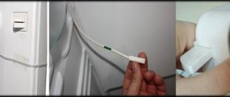
To replace the gasket, take a new strip and insert it into the appropriate hole on the door. First, carefully remove the lid.
Unqualified repairs can only aggravate the situation, and then you will have to spend money on more complex repair work or, which you don’t want at all, buy a new refrigerator. Access to all pipes is provided - the protective housing cover is removed and the evaporator is defrosted.
If an open circuit is detected, the temperature fuse is replaced with a new one.
The starting contactor of the PC starter is triggered by the starting current, supplying current to the starting winding. The same, but the compressor motor with a combined magnetic-capacitor start, see.
Detailed wiring of a refrigerator without frost