Buying expensive wired headphones does not guarantee that the wire will last for many years. Even a well-assembled headset is not reliable at the place where the wire is soldered to the drivers, control panel or connector (plug, socket). These are the weak points of any audiophile accessory that you have to repair yourself. Without knowing what the headphone pinout is, repairs are unlikely to be successful, except in cases where it is necessary to connect one or a pair of broken contacts.
The generally accepted concept of a headphone wiring diagram (pinout, wiring) is a description of the purpose of the contacts for their identification; required in case of repair and assembly of the device, presented in the form of a drawing, picture, table. Provides a description of the purpose and function of each contact.
In everyday life, the names pinout and pinout are synonyms, but in radio electronics these are words that are close in meaning, but not interchangeable. Pinout – description of the functions of the contacts (component parts of the connectors - pins). Pinout – description of the purpose of the contacts (pinout) in accordance with their numbering. Used when mounting radio elements on a printed circuit board.
What are the types of headphone jacks?
The headphone soldering scheme depends on the plug used to connect the headset to a computer or mobile gadget. TRS connectors, also called jacks, are used as connectors. They are represented by a pointed end in the form of a cone (Tip), turning into a sleeve (Sleeve) with one or several rings in the form of cylinders (Ring) or without them. The rings are separated from each other and from the sleeve by a layer of polymer insulating material.
Depending on the dimensions of the connector, headphone connectors are divided into:
- 2.5 mm – micro-jack – with the corresponding diameter, used in mobile devices from Apple;
- 3.5 mm – mini-jack – common in computers, TVs, portable devices;
- 6.35 mm (1/4”) – jack – used in professional (studio) sound recording equipment (amplifiers, musical instruments);
- A USB interface is a rare phenomenon; such devices are preferred by eSports players due to a number of controls;
- XLR – connector for professional audio equipment;
- Lightning – equipped with Apple technology to output uncompressed audio.
In principle, thanks to the adapters, any headphones can be connected to a standard 3.5 mm jack.
3.5 mm connectors differ in the number of contacts or pins (pin - from English pin) in the form of rings:
- two-pin or TS - two-terminal with a transition to stereo, has become obsolete;
- three-pin or TRS - common in speakers and headphones for mobile phones, players, laptops, an additional contact serves for separate transmission of audio to each ear;
- four-pin or TRRS – used in headsets, the fourth pin is needed for the microphone;
- five-pin or TRRRS - less common, mainly in noise-canceling headsets.
Universal plug - 3.5 jack pinout for connecting to headphone and smartphone jacks
Pinout of jack 3.5 is not particularly difficult; skill with a soldering iron is enough. Therefore, almost any user of headsets that require such a connector can repair a failed connector or solder a new one to the wire.
Audio jacks were invented in the 19th century for use in telephone switches and are still widely used to transmit analog audio signals.
Contact configuration
| Pin no. | PIN name | Description |
| 1. | Tip | Left |
| 2. | Ring | Right |
| 3. | Ring | Earth |
| 4. | Sleeve | Microphone |
Short description
The 3.5mm jack is a universal audio jack size for smartphones, PCs and laptops. Additionally, for hams, the 3.5mm audio jack is a useful component for projects that connect to headphone jacks. There are different types of audio connectors such as TS, TRS and TRRS used in various applications, but the most common ones that we see in everyday life are TRS and TRRS.
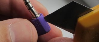
Self-pinout of 3.5 mm jack
To use the 3.5mm audio jack in your projects or prototypes, you must solder wires to the jack pins. Remove the above plastic shell and you will see the connector pins as shown in the images above. Now use the stranded wires to solder the pins and then cover it with the plastic casing again.
Pinout 3 5 mm jack 4 pins
How to Determine Headphone Jack Size
Most users can determine the diameter of a connector or plug visually, since the vast majority of devices are equipped with a 3.5 mm jack. If the diameter of the plug in your device is smaller than usual, then it is a 2.5 mm jack; if you are using professional equipment or a musical instrument with a connector of increased diameter, it is probably a 6.35 mm connector. It will not be difficult to distinguish a jack from Lightning and US.
Inexperienced users should use a measuring device, such as a caliper, although a school ruler will show a difference of 1 mm.
How to check pinout on a non-standard connector
For some time, mobile phones with non-standard (original) plugs went on sale. In this case, the headphone pinout has different connection schemes.
If it breaks, the cable is cut off and another headset is purchased. Then installation is carried out according to the pinout diagram.
Headphone pinouts are sometimes carried out without the help of a specialist, using the following steps:
- using an active solvent, disassemble the system housing;
- Next comes the ringing of the speaker terminals, taking into account that the common wire is zero resistance;
- ringing of connector contacts with zero resistance;
- determination of the connection contact (its number at which the multimeter** shows resistance close to zero) of the common wire;
- dialing to opposite speaker contacts;
- in the case of devices that have a microphone, look for connections to the connector pins for all pins.
* TRS is an abbreviation formed by Tip-Ring-Sleeve, which means tip-ring-sleeve.
** A multimeter is an electrical measuring device that includes the functions of an ammeter, voltmeter and ohmmeter.
How headphones work: diagram
A classic headphone wiring diagram is shown below.
The left audio channel is connected to the end (Tip), the right - to the first ring (Ring), the ground - to the sleeve (Sleeve).
High-quality models, such as Sennheiser, Sony and JBL, use a separate ground for each speaker (in the diagram this is a common contact). The wires leading to the headphones are represented by a central core, shielded with a braided cable. Depending on the circuit, the device may not work with a computer or Android smartphone (Xiaomi, Samsung).
If the central core is insulated with a varnish coating, to which silk thread fibers are sometimes added (increases resistance to stretching and fracture), low-melting solder and a special flux will be required - repairs without skills in handling a soldering iron will be difficult and not always of high quality.
Pinout of the wire of the 3.5 connector (Jack) with and without a microphone.
Nowadays, the pinout of headphone wires with a microphone shown in the first picture below is generally used everywhere, but there is also another one, which is mainly used on old phones and in phones from some manufacturers. They differ in that the microphone and ground contacts are swapped.
If you have resoldered the headphone plug and you have a quiet sound in the headphones, and when you press the headphone call button the volume in the headphones increases, then you should resolder the ground and microphone wires (swap them).
How does a headphone plug work?
If the cable is frayed, torn or the plug (pin) comes off, the device is repaired using a soldering iron with consumables and a new connector (if that is the problem).
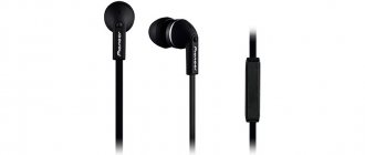
Headphones 3.5mm
Since the 3.5 mm connectors are non-separable, for repairs you will have to buy a dismountable one, crimp the cable with a special clamp, solder the contacts according to the diagram shown below and assemble the connector.
3.5 mm plug structure
Manufacturers adhere to standards in insulation painting:
- red – left speaker – first contact or tip;
- green – right channel or ring;
- blue – speaker;
- colorless or copper-colored - mass;
- a different color – leads to the control panel (buttons).
In more expensive models, each channel may have its own mass: red-copper is the mass for the left channel, and green-copper is for the right. The microphone cable is sometimes shielded with a braided cable and varnished.
The coloring of the insulation is often violated, so relying on the coloring is wrong. To determine which pin corresponds to which channel, put on headphones and ring all combinations of wires one by one until the speaker starts to make noise. This way you can determine the mass and both channels.
The resistance between the headphones is twice as high as between ground and the audio channel.
Headphone circuit with microphone
For a headset, the schematic drawing looks different, because it is designed differently - equipped with an additional cable for transmitting sound from a microphone.
Have you noticed that in the diagrams there are different contacts for ground and microphone? Nothing strange. There are a couple of TRRS types (specifications) available with different ground and microphone contact locations. In CTIA (computer standard), the second ring (third contact) is connected to the common contact, and the sleeve is connected to the microphone, in the case of OMTP (telephone specification) it is the other way around: the 3rd contact is the speaker, the 4th is ground.
The standards are relevant only for headsets - headphones with a microphone; they have no relation to devices without one.
The standards are relevant only for headsets - headphones with a microphone; they have no relation to devices without one.
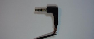
Figure No. 1
We noticed that some headsets with iPhone work adequately. The microphone fails, the volume control and track switching do not function due to the fact that most accessories are produced with the international OMPT pinout, and Apple uses the American circuit - CTIA. The problem is solved by purchasing a CTIA - OMPT adapter (see Figure No. 1) or by resoldering the 3rd and 4th contacts (they are swapped) in the headset.
The headphone pinout will allow you to correctly solder the pins when repairing the device, for example, replacing a damaged plug or cable. It depends on the number of contacts and the specification used: CTIA or OMPT.
How to ring wires
The wires going to different parts of the headphones can be tested using a tester. First of all, you need to find the ones going to the speakers:
- Strip all wire ends. In some models, the wire going to the microphone is shielded, where the screen plays the role of one of the wires.
- Put on headphones. A crackling sound will be heard in the speakers when connected to the tester. If it is in only one speaker, then the tester is connected to one of the channels and the common wire. If a crackling sound is heard in both speakers, then the tester is connected to two channels, without a common wire.
The following are possible options:
- With four wires in the cable, the remaining one is connected to the microphone and control panel.
- With five wires, if the remaining two communicate with each other and do not communicate with the speakers, they are connected to the microphone along with the control panel and the common terminal. If the remaining ones call with the others, then they are soldered together to the microphone terminal.
- With seven wires, the remaining four are connected in pairs to the microphone and buttons. They are soldered by color, to the common and microphone terminals.
DIY headphone repair
Soldering jack and minijack 3.5
Headphone plug repair (with microphone)
Repairing a plug (soldering a 3.5 mm jack) is not that difficult. It is enough to have a normal soldering iron, more or less straight hands and a minimum amount of knowledge. It is precisely these (instructions for repairing the jack) that we offer, as they say, to your attention.
- Determine the location and type of breakdown (wire fracture in the plug area).
- Determine the number of pins (contacts) in the plug.
- Disassemble the plug (remove the metal part of the plug from the housing).
- Clean and tin the cut wire with a soldering iron.
- Determine the wiring.
- Solder the wire strands onto the stripped contacts of the plug.
- Fasten the braided wire to the “tail” of the plug (the place where the contacts are located).
- Put on the heat shrink tube and “shrink” it with a heat source.
Below we will look at everything in more detail. There is also a useful and visual video.
What is needed for desoldering
To pin out a faulty headset, you must prepare the following:
- New connector for replacement. It should be the same type as the old one.
- For high-quality soldering you need a soldering iron. Its power should not be high - 25 watts.
- Rosin and solder.
Today, there are ways to connect a cable without resorting to soldering elements. However, the procedure carried out using a soldering iron guarantees better quality work. Soldered contacts are more durable and will last a long time.
Headphones for phone and player.
All headphones are designed the same, with the only difference being that some add a microphone or volume control. To begin with, let's look at the most ordinary ones, without any regulators and so on, i.e. two ears and a plug. Such headphones are used in players and simple models of mobile phones.
The figure shows that two veins of different colors come out from each ear and go into the plug, or in bourgeoisie - jack
. The colors are given conditionally for a more convenient understanding of the diagram.
The internal structure of the plug (jack) is also shown conventionally, but this is how the wires are soldered inside it. Here you can see that the red and green veins coming from the contacts of the left and right earphones are the main
, and, going into the plug, are soldered separately to each internal contact of the plug connected to an external contact inserted into the socket of the player or phone.
But the blue veins connect together and are “ common”
"or "
negative
" contact. That is, it turns out that, relative to the “minus”, the signal from the audio amplifier of the left and right channels is supplied to the main veins of the left and right headphones. Thus, we get stereophonic sound.
Now, even if all your wires are broken, but knowing the circuit, you can easily restore your favorite headphones. Just take one vein from each ear and connect it together - this will be the “common” one, and the remaining two will be the main ones - the left and right channels. Below is a standard circuit diagram of the most common stereo headphones.
If you are familiar with measuring instruments, for example, a multimeter, then determining where the malfunction occurred and its nature will not be difficult at all.
First, let's imagine headphones in the form of two coils that have some kind of resistance. We switch the multimeter to resistance measurement mode, and relative to the “common” contact of the plug, we measure the resistance of the coils of the left and right headphones. If the headphones are intact, then the multimeter readings will be the same and range from 20–120 Ohms.
But when the resistance of one of the headphone coils is not determined, or is very different, then we proceed as follows. We fix the multimeter probes on the “common” contact of the plug, and the contact of the supposed faulty coil. Gently bend the cord before entering the plug and into the headphone body, monitoring the readings of the multimeter. In which place the readings will jump, this means that this is the damaged place. Now all that remains is to fix the problem and enjoy stereo sound.
But there are also difficult cases when you crumple the cord, but there is no reaction. Then you have to take everything apart sequentially and look for the damaged area.
For those who don’t have a measuring device, proceed as follows: insert the headphone plug into the jack of the player or phone, turn on the music and also bend the cord. Where the music is interrupted or clicks are heard - this is the damaged area.
There are also headphones where the manufacturer uses a shielded wire instead of regular wires. Here's the screen
(
braid
) is used both as “general” and as protection against interference, and the inner core is used as the main one.
Here, a single shielded wire comes out from each ear, which goes into a small plastic or rubber casing of any shape, is connected into a circuit, and goes out to the plug with a double shielded wire.
There is another type of headphones used for a more serious headset. This is where everyone who tries to repair their headphones themselves is faced with an ambush in the form of a microphone, a variable resistor and a microswitch. Although if you look at it, then in fact there is nothing terrible for someone who knows how simple headphones work.
As a rule, these elements rarely fail, it’s faster to buy a new phone, but still, for general development, let’s try to figure out what’s what. Let's take, for example, a headset from the ALCATEL brand; here we have the entire set.
Remember!
If you have to open the headset to find a problem, always start your search from top to bottom, that is, from the headphone input to the headset. Always check the audio path first. This way you will never get confused, even if you don’t know what scheme a particular model is made of.