Homemade compressor
An air pump is a useful tool in a car enthusiast's garage. They are not only convenient and easy to inflate wheels, but can also blow out a carburetor, a pipe... and any surface that can be used for a spray gun. Of course, there are many applications for a compressed air stream, but to operate, for example, a jackhammer, the performance of this compressor will not be enough. It is very easy to make a compressor from a refrigerator with your own hands. Many people know how to do this, but not everyone knows how to properly operate the device. Today we propose to start considering the problem with a minimum set of accessories that together will make an excellent compressor!
Compressor from an Oka refrigerator
Many people have an unnecessary refrigerator (or compressor) and a gas cylinder.
To inflate the wheels, you can use one compressor, without a gas cylinder.
From these we will make a compressor:
The engine was removed and the tubes were carefully sawed off.
I changed the oil - sawed off the plug, drained the old oil and poured in about 60 grams of 10W40 oil (semi-synthetic).
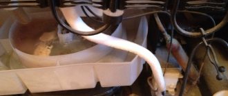
I put a piece of rubber hose with an internal diameter of 6 mm and a gasoline filter on the thin retractor tube, clamped it with clamps, put an 8 mm hose on the discharge tube, then a flexible hose, clamped it with clamps.
A flexible hose was threaded to the head of the receiver.
The gas cylinder was steamed over a fire for about half an hour, open .
It is very dangerous for life, it is better to find an already steamed one or a new one.
Then he turned off the faucet. More precisely, he sawed it off with a grinder - he didn’t want to unscrew it. And welded a 1-inch barrel. Although it is cast iron, it was welded perfectly with a semi-automatic machine.
Then I screwed the head of the receiver (sold) through the fum tape, screwed into the head a pressure switch, a pressure gauge, a flexible hose from the compressor, at the outlet an adapter from an inch to 1/2 inch, a faucet, an outlet from a flexible hose and a long 8 mm hose through a clamp. .
It works great - it pumps 4 atmospheres in 20 minutes, then turns off until the pressure drops to 2 atmospheres.
True, unfortunately, working with a spray gun lasts about 5 minutes, then again you have to wait for pressure.
The compressor turned out to be very convenient! You will be pleased with the fact that some DXM allows you to obtain a pressure of about 10 atm, while special professional stations are often made for 2 atm, but a factory compressor also has a number of advantages.
Compressor connection diagram
Electrical connection diagram:
with starting and running capacitors (capacitance depending on motor power)
Typical circuit with start-protection relay
Compressor from a ZIL refrigerator
It pumps slowly, of course, but I thought it would be worse (8 liters 7 kg/cm2 - 4:30).
I didn’t set the pressure release after switching off; the plastic input to the relay was broken. The tubes are led out into a 1/2-inch thread, so oil vapors will not be sucked in.
There are so many options, but there will always be people who will do something of their own—new.
Description of the compressor device
To make a compressor with a receiver we will need:
- Refrigerator relay;
- Pressure switch;
- Quick release 1/4;
- Hose 200 mm 1/2;
- Receiver - fire extinguisher 8 liters;
- Compressor - “ZIL”;
- Air filter - Donaldson P550440 (3/8 thread, slightly different pitch);
- Legs - Volga silent blocks + hose;
- Check valve 1/2;
- Wheels;
- Fittings, 1/2 threads.
Making a compressor in pictures
SHARE WITH YOUR FRIENDS
Refrigerator compressor device
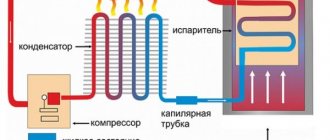
A fundamental physical rule also applies in everyday life: heat is transferred from a body with a higher temperature to a body that is less heated. In order for the reverse process to occur and cold to be created in a household appliance, external energy must be applied in the form of mechanical work.
This is exactly how refrigeration systems operate. Electricity powers a special device that creates pressure and compresses the refrigerant gas to convert it into a liquid state. Such a part is the compressor, which is often called the “heart of the refrigerator.” After all, if it stops working normally, the process of generating cold is impossible. In addition to compression, other types of installations are known (absorption, thermoelectric), but they cannot be found in household solutions for the home.
By design, compressors are most often an electric motor driving a single-cylinder piston pump with a valve mechanism. Less common are linear-type installations, where there are no rotating parts, and the pump piston vibrates from the reciprocating movements of the electromagnetic coil core. However, these devices are not so common; they are practically not found on older models of refrigerators.
Another type of drive is systems with frequency control of engine speed, which are otherwise called inverter systems. Structurally, these are the same electric motors with windings, but the current supply circuit to them is much more complicated than the usual one. Modern electronic control boards convert the alternating voltage of a household network of 50 hertz into direct current, which is then again transformed into a periodic form, but with changeable parameters.
Inverter compressors are considered the most advanced type of technology, having a number of noticeable advantages over previous models. They are produced today by leading companies in the industry:
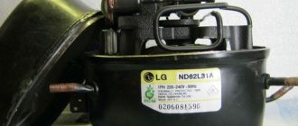
- LG;
- Liebherr;
- "Bosch"
- "Indesit".
However, the downside is their excessive complexity, which does not allow diagnosing and repairing the system at home with your own hands.
When a refrigerator with an inverter compressor breaks down, you should not try to do anything with it yourself; contact qualified service technicians. If the installation is of a conventional type with direct power supply from 220V, there is a chance to start a jammed refrigerator compressor without resorting to outside help. Traditionally, domestic brands of equipment (Atlant, Sviyaga) are more suitable for DIY repairs.
Where is the compressor located?
The compressor engine, together with the piston pump, valve mechanism and freon receivers, are usually installed on damping springs inside a hermetically welded metal casing. This part is usually painted black for better heat transfer and looks like a round tank with tubes coming out of it. Place it in the back wall of the refrigerator on a metal frame near the condenser (a coil of tubes that dissipates excess heat).
The pressure inside the sealed compressor housing during normal operation is 10 atmospheres. Power is supplied to the motor through contacts on the outer wall of the tank.
Checking the compressor for functionality
The result of normal operation of the compressor is the creation of the required refrigerant pressure in the pipe system. This indicator varies for different models, but it is fundamentally believed that if the output pressure is less than 4 atmospheres, the device is unsuitable for operation.
You can directly verify the performance of the motor by measuring the pressure only by cutting through the freon tubes. After this, the refrigerant will escape outside, and home repairs will become impossible. To re-solder the line and pump freon into the system, you will have to invite a specialist with equipment. Although some owners of old refrigerators make air pumps from their compression chambers for home use - working with a spray paint gun or inflating wheels. In these cases, the device is checked by direct pressure measurement.
If the purpose of the repair is an attempt to restore normal operation of the refrigerator, the condition of the compressor will have to be assessed by indirect signs (noise, vibration). According to reviews from experts, the two most common breakdowns are:
- malfunction of electrical equipment, including failure of the start-up relay;
- jamming of the mechanical part of the compressor (the rotor of its engine or the piston in the pump cylinder).
The system is checked separately for each of these problems to understand which part requires repair or replacement. To do this, you will need to directly start the refrigerator compressor without a relay.
P O P U L A R N O E:
In some models of welding inverters, for example Helper Prestige, ProfHelper, BestWeld, etc., belonging to the conventional TECNICA family, a control unit submodule S20609 .
Its repair will be discussed in the article below...
DIY crafts from old car tires
It's winter, but we'll remember the warm green summer!
If your family has a car, then there will always be old unnecessary tires. The car has no use for them anymore, but they will come in handy for us... Crafts made from tires are not only a nice decoration for your garden or dacha, but also a good functional help in the household. These are not only flower beds and flower beds, you can also make a bench, a washbasin, or even... a bicycle parking lot by digging a few tires into the ground. You can use your imagination and come up with anything...
Electrical equipment of compressors, fans, their automation, control circuits
Most compressors and fans run on a conventional asynchronous motor. It follows from this that the engine control circuit is classic. Below you will find them with descriptions. If you are interested in the Levenhuk Skyline Travel 70 telescope, you can purchase it by clicking on the link.
Design and principle of operation of asynchronous electric motors
- The rotor is also the core. It is supplied with input voltage. It can be short-circuited or phase. In the first case, the central rod is cast from aluminum with short-circuited rings at the end. Otherwise this type is called a squirrel cage. In the second case, 3 copper windings are used.
- Stator. This is the outer cylinder that is “put on” the rotor. It receives voltage from the rotor, which causes it to rotate. As a rule, it is made from steel sheets with grooves into which copper winding is laid.
- Other details. This includes shafts, bearings, bushings and other parts that are not directly related to electromechanical rotation. Also included in this category is the metal motor housing.
The principle of operation of an asynchronous machine is implied in its name. The rotation speeds of the rotor and stator are different, unlike synchronous motors.
The step-by-step process looks like this:
- When current is applied to the rotor, its magnetic field (hereinafter referred to as m.f.) excites the stator circuit. In this way, an electromotive force is induced.
- Alternating current is generated in the rotor.
- Rotation 2 m.p. create torque, but the speed is different.
In this regard, the compressor and fan control circuit, according to GOST requirements, must have:
- smooth start;
- security system against current and voltage surges;
- ability to switch between automatic and manual control (optional);
- automatic control of the air/liquid injection process.
If you want to imagine the action better, you can watch this video.
Asynchronous or collector: how to distinguish
In general, you can distinguish the type of engine by the plate - the nameplate - on which its data and type are written. But this is only if it has not been repaired. After all, anything can be under the casing. So if you are not sure, it is better to determine the type yourself.
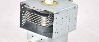
This is what a new single-phase capacitor motor looks like
How do collector motors work?
You can distinguish between asynchronous and commutator motors by their structure. The collectors must have brushes. They are located near the collector. Another mandatory attribute of this type of engine is the presence of a copper drum, divided into sections.
Such motors are produced only as single-phase ones; they are often installed in household appliances, as they allow one to obtain a large number of revolutions at the start and after acceleration. They are also convenient because they easily allow you to change the direction of rotation - you just need to change the polarity. It is also easy to organize a change in the rotation speed by changing the amplitude of the supply voltage or its cutoff angle. That is why such engines are used in most household and construction equipment.
Commutator motor structure
The disadvantages of commutator motors are high operating noise at high speeds. Remember a drill, an angle grinder, a vacuum cleaner, a washing machine, etc. The noise during their operation is decent. At low speeds, commutator motors are not so noisy (washing machine), but not all tools operate in this mode.
The second unpleasant point is that the presence of brushes and constant friction leads to the need for regular maintenance. If the current collector is not cleaned, contamination with graphite (from brushes being worn out) can cause adjacent sections in the drum to become connected and the motor simply stops working.
Asynchronous
An asynchronous motor has a starter and a rotor, and can be single or three phase. In this article we consider connecting single-phase motors, so we will only talk about them.
Asynchronous motors are characterized by a low noise level during operation, therefore they are installed in equipment whose operating noise is critical. These are air conditioners, split systems, refrigerators.
Structure of an asynchronous motor
There are two types of single-phase asynchronous motors - bifilar (with a starting winding) and capacitor. The whole difference is that in bifilar single-phase motors the starting winding works only until the motor accelerates. Afterwards it is turned off by a special device - a centrifugal switch or a start-up relay (in refrigerators). This is necessary, since after overclocking it only reduces efficiency.
In capacitor single-phase motors, the capacitor winding runs all the time. Two windings - main and auxiliary - are shifted relative to each other by 90°. Thanks to this, you can change the direction of rotation. The capacitor on such engines is usually attached to the housing and is easy to identify by this feature.
You can more accurately determine the bifolar or capacitor motor in front of you by measuring the windings. If the resistance of the auxiliary winding is less than half (the difference can be even more significant), most likely this is a bifolar motor and this auxiliary winding is a starting winding, which means that a switch or starting relay must be present in the circuit. In capacitor motors, both windings are constantly in operation and connecting a single-phase motor is possible through a regular button, toggle switch, or automatic machine.
Read also: How to charge a screwdriver without a charger
Control sequence blocking circuit for two electric motors
Below is a control diagram for a compressor installation for several engines:
- Q – switches;
- F – fuses, in case of a sudden surge in current;
- KM – magnetic starters that prevent the simultaneous operation of 2 motors;
- KK - thermal relay that reacts to the heating of the motor and turns it off;
- SBC – mechanical switches, in case of an emergency;
- SBT – mechanical switches;
- Q3 – auxiliary switch, in case of failure of the first ones.
Additional circuits can be included in the electric motor control circuit as the number of motors increases.
Automatic control circuit
The disconnected relay bypasses resistors 1-2, and now the asynchronous machine begins to accelerate from resistors 2-4. The contactor then turns off the second relay.
Thus, the relay is gradually turned off and the acceleration on the resistors is shifted. This occurs until all resistors are completely bypassed and the motor reaches operating speed.
This is a relatively simple automation scheme that any compressor can work with.
Circuit for controlling a pump motor with a pressure function
- Shutdown - when the liquid level in the container increases;
- Switching on - when decreasing.
The compressor connection diagram is convenient in that it implies both automatic and manual control.
The electrical circuit looks like this:
Elements with the initial K are manual switches. When using it, they are transferred to the lower position. When you press the mechanical switch KpN, the current flows to L1 and the motor starts.
If you want to use automatic shutdown, the K elements move to the up position.
System Maintenance and Lubrication
To ensure proper lubrication, the compressor should not operate at speeds lower than 400 rpm or higher than the maximum permissible speed to avoid rapid wear of parts. The oil level should always be maintained at medium level. Never allow the oil to drop below the marked level. An oil change should be performed after the first 100 hours of operation and every 1000 hours thereafter. Only fill the crankcase when the compressor is switched off.
The lubricating oil must be of superior quality, free from rust or oxidation inhibitors. Using the wrong oil can contaminate piston rings and clog heat exchangers, control lines and relief valves. Technologists recommend using lubricants with a viscosity index not exceeding 100 mm2/s at 40 degrees Celsius to fill the piston group of a compressor unit.
The procedure for replacing/topping up oil is as follows:
- Unscrew the drain plug on the oil pan, let all the oil flow out, and screw the drain plug back on.
- Fill oil into the top hole of the oil pan to the center mark.
- Check the oil level using the dipstick.
Scheme for automatic compressor electric drive
A similar combined electrical circuit has manual control (using the KUP and KUS buttons) and auto control, based on the pressure in the container.
The control circuit diagram looks like this:
To enable manual control, the “P” component is placed in the “Manual” position. When B closes, relay 1 is activated. From it, current flows to the “computer” valve, which opens the water flow. The second relay opens the air supply.
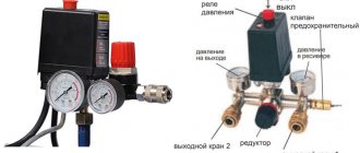
Compressor Connection Diagram
Other names are telepressostat and pressostat.
After some time, the K contacts open and the KU contacts close. In this case, independent adjustment of the actuator will be relevant. However, sometimes situations arise in which it is necessary to adjust the device yourself: Adjustment after partial or complete repair. Start the motor - compressor from the refrigerator without a relay
When the slider moves to the right, Rv immediately opens, but this does not affect the operation of the engine, since contactors L1, L2 receive power through the economic resistor Re1 and block contact L2.
The use of single-phase switches for three-phase loads is unacceptable, since one of the phases remains permanently connected to the winding. Automated control schemes In Fig.
Detailed description of the pressure switch for a compressor video Connection diagram Pressure switches for compressors can be for different load connection diagrams.
In emergency situations, when the pressure level is higher than the permissible norm, and the telepressostat does not work, the safety unit comes into operation and vents the air. Thermal relay.
Check the atmospheric pressure. In accordance with the rating of the power supply line, the appropriate model of the relay unit is selected. Electric motor connection diagram FUBAG Compressor
Refrigerator engine starting circuit without starting relay
To try to start the compressor from a refrigerator without a relay, assemble a simple circuit from a 220 V power cord, onto which you install contact terminals or alligator clips. Determine which of the outputs on the tank body belongs to the working winding and which to the starting winding. This is done by measuring the resistance between the common contact and each of the two remaining ones - the readings in the working circuit should be lower than in the starting circuit (for different models 10-15 and 25-30 ohms, respectively).
Connect the 220 V power supply to the common output contact and the working winding. After this, use a suitable tool (a screwdriver with an insulated handle) to briefly short-circuit the starting winding with the working winding (a careful electrician will use a non-locking button). This way, a working refrigerator motor will start without a relay.
If there is no sound of the compressor running, the motor is jammed. This often happens on older cars due to general wear and tear, lack of oil in the crankcase or broken valve plates of the piston pump.
Some craftsmen try to wedge the electric motor by making a circuit of two powerful diodes connected to its windings, directed in opposite directions. If the cause of the “wedge” is in the rotor bearings and not in the piston bearings, sometimes this is successful. After wedging, the refrigerator is started again without a start relay in order to finally understand what the breakdown was. But if the “wedge” occurs due to lack of oil in the compressor, you can no longer do without professional help, because the cause has not been eliminated.
Related Posts
It must have the required pressure. However, it is not always possible to replace elements - some modifications are no longer available for sale. To eliminate this type of malfunction, you can use one of the following methods: clean the surface, which extends the service life by at least 3 months, or repair it by replacing the contacts in the terminal clamps . For a single-phase motor, a volt relay is used, with two groups of connections.
Frequent starting of the motor.
During operation, the indicators formed as a result of the elastic force of tension or compression of the springs and the pressure of the atmosphere pressed by the device are compared. The container membrane is connected to the pressure switch. The contact of this relay supplies power to the computer solenoid valve, which allows cooling water to enter the compressor compartment. The author of the article describes in detail the existing types of pneumatic relays.
Below is a diagram of connecting automation to three phases. In accordance with the rating of the power supply line, the appropriate model of the relay unit is selected.
Remember that the compressor should be depressurized no earlier than 5 minutes before soldering. Share your own experience in operating a compressor with a pressure switch, ask questions, post photos on the topic. Working and starting capacitors for teapots.
Air relay connection diagrams
The compressor pressure switch is manufactured for connection to electrical circuits of different loads. In accordance with the rating of the power supply line, the appropriate model of the relay unit is selected.
Option #1: to a network with a nominal value of 220 V
If the drive motor is a single-phase device, then a 220 V relay with two groups of contacts is installed.
Option #2: to a three-phase network with a voltage of 380 V
For a three-phase load of a 380 V circuit, one of the options can be used: a modification of the relay for 220 V or 380 V, with three contact lines, to simultaneously disconnect all three phases.
Both methods have different schemes. Let's consider the first option:
By choosing the second method, power is supplied from one phase (zero) and in this case the relay rating should be 220 V. For more details, see the following diagram:
After connecting to the power supply, you need to understand the additional capabilities provided in the air blocks for ejectors.
Principle of operation
Unsolder the tubes from the compressor and condenser, unsolder the filter drier.
Since the air pressure regulator is connected to the receiver, the compressed air from it enters the membrane relay unit.
Solder a new filter drier. In Fig. When the compression level in the receiver decreases, the membrane installed in the pressure regulator bends down. Even with extensive experience, such a mechanism is difficult to manufacture. Adjust the parameters of the highest and lowest pressure in the system using the adjusting screws. According to the factory standardized settings, the elasticity coefficient is set to the pressure in the pneumatic chain, as reported in the instructions for the device. More specifically, one phase will be permanently connected to the load. After connecting to the power supply, it is necessary to understand the additional capabilities provided in the air blocks for ejectors.
Be sure to disconnect the device from the power supply and remove the cover from the pressure switch. It should not be directed inside the pipes, since the plastic elements of the units may become deformed or even melt due to heating. A large screw clamp and spring are provided to control compression settings. Identified by a characteristic whistle and the feeling of a sharp cold draft near the body.
Maintenance Actions - Inspection Schedule
Every 50 hours of operation the following should be done:
- Drain water condensate accumulated in the air receiver using a drain valve.
- Cleaning the air filter elements when using the unit in a dusty environment.
- Check the oil level according to the indicator on the crankcase and, if necessary, add oil to the acceptable level indicator.
Every 100 hours of operation the following is carried out:
- Clean the air filter elements even when the compressor is not used in a dusty environment.
- Change the lubricating oil if a lubricating oil with minimum characteristics is used.
- Lubricate the drive belt to extend its service life.
- Filling with oil without exceeding the maximum indicator level.
Every 500 operating hours:
- Replacement of air filter filter elements.
- Checking the operation of the compressor unit at rated pressure.
- Check the tightness of all ties and fasteners.
Every 1000 hours of operation the following is performed:
- Change the oil if a synthetic type of lubricant is used.
- Filling with oil without exceeding the maximum indicator level
- Checking the operation of the compressor unit at rated pressure.
- Replacement of air filter filter parts.
Purpose
After the compressor engine starts, the pressure in the receiver begins to increase.
If the excitation rheostat slider R is moved, then a resistor will be introduced into the SHOV winding circuit. The presence of a free connector allows you to install the control pressure gauge in a place convenient for the user. Control the pressure using the pressure gauge and set the required values.
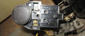
Other names are telepressostat and pressostat. To do this you will have to: Disconnect the wiring from the contacts; Cut through the motor tubes connecting it to other parts; Image 4 - biting the motor tube Unscrew the mounting bolts and remove from the casing; Disconnect the relay by unscrewing the screws; Image 5 - disconnecting the relay Next, you need to measure the resistance between the contacts; By applying the tester probes to the output contacts, normally you should get OM depending on the model of the engine and refrigerator. The working system consists of springs of different levels of rigidity that respond to changes in pressure.
There may also be other auxiliary mechanisms that require activation: a safety or unloading valve. Types of pressure switch devices There are only two variations in the design of the automatic compressor unit. With the help of a relay, it becomes possible to operate automatically while maintaining the required compression level in the receiver.
Complete set of compressor automation unit
The relay design is a small-sized block equipped with receiving pipes, a sensing element (spring) and a membrane. Mandatory subassemblies include an unloading valve and a mechanical switch.
The pressure switch sensing unit is made up of a spring mechanism, the compression force of which is changed by a screw. According to the factory standardized settings, the elasticity coefficient is set to a pressure in the pneumatic chain of 4-6 at, as reported in the instructions for the device.
The degree of rigidity and flexibility of the spring elements is subject to the temperature of the environment, therefore absolutely all models of industrial devices are designed for stable operation in an environment from -5 to +80 ºC.
The reservoir membrane is connected to the relay switch. During movement, it turns the pressure switch on and off.
The unloading element is located between the ejector check valve and the compression block. If the motor drive stops working, the unloading section is activated, through which excess pressure (up to 2 atm) is released from the piston compartment.
With further start or acceleration of the electric motor, a pressure is created that closes the valve. This prevents overloading of the drive and simplifies starting the device in switched off mode.
There is an unloading system with a time interval of activation. The mechanism remains in the open position when the engine starts for a specified period. This range is enough for the engine to achieve maximum torque.
A mechanical switch is required to start and stop the automatic system options. As a rule, it has two positions: “on.” and "off". The first mode turns on the drive and the compressor operates according to the established automatic principle. The second one prevents accidental starting of the engine, even when the pressure in the pneumatic system is low.
Safety in industrial structures must be at a high level. For these purposes, the compressor regulator is equipped with a safety valve. This ensures system protection in case of incorrect relay operation.
In emergency situations, when the pressure level is higher than the permissible norm, and the telepressostat does not work, the safety unit comes into operation and vents the air. Safety valves in heating systems operate according to a similar scheme, the operating principles and devices of which are described in the article we recommend.
Optionally, a thermal relay can be used as additional protective equipment in the review device. With its help, the strength of the supply current is monitored for timely disconnection from the network when parameters increase.
To avoid burnout of the motor windings, the power is turned off. The nominal values are set using a special control device.