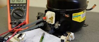
For a three-phase motor, the presence of a starting winding is an unnecessary element. Consuming 380 volts, it is connected directly to the network, the stator coils are phased in a certain way. Requires starting from a 230 volt network - craftsmen begin to use chemicals. Star and delta circuits appear, using a capacitor that provides a voltage shift of 90 degrees in an arbitrary winding relative to the remaining two. The first one acts as a starting one; the capacitor should turn off when the engine picks up speed. In fact, a three-phase motor turns into a two-phase one. Of course, you can make a power supply that produces three sinusoids, artificially shifted 120 degrees relative to each other. The start-up protection relay of the refrigerator echoes the operating principles of asynchronous motors and serves to implement the functions implied by the name.
Refrigerator start relay connection diagram
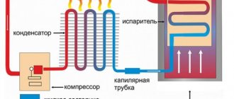
This part is needed to start an asynchronous single-phase compressor motor. There are no difficulties in connecting the relay. The starting and operating windings are connected to the motor stator. The first is involved in starting and starting the compressor, the second keeps the rotor in working condition and continuously supplies alternating current. There is a start-up relay that regulates the supply and turns off the power to the working and starting windings.
Inductive short circuit
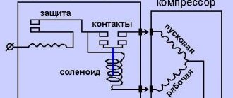
Power is supplied to the input of the device: “zero” and “phase”, at the output the latter is divided into 2 lines. One is connected to the starting winding through the starting contact, the other is connected to the working winding of the motor. In the relay, current is supplied to the working winding through a spring, the resistance of which is quite high, then through a connection with a bimetallic jumper. This element has the property of bending in one direction under the influence of elevated temperature. As soon as the current in the circuit increases significantly, for example, if a short circuit occurs between the turns or the motor jams, the spring that comes into contact with the jumper heats up. The latter changes shape, after which the contact opens and the compressor turns off.
In order to start the motor in this circuit, a coil is used, connected in series with the working winding. When the rotor is stationary, voltage is applied, which causes an increase in the current in the coil. A magnetic field is formed, it attracts the movable core, which in turn closes the starting contact. After the rotor picks up speed, the current in the network decreases and the magnetic field decreases. The starting contact is opened by a compensating spring or gravity.
Posistor switching
The starter consists of a capacitor and a posistor, which is a type of thermal resistor. In the compressor circuit, the capacitor is installed between the buses of the starting and working windings. This mechanism provides the phase shift necessary for the compressor motor to turn on. The posistor is connected in series with the starting winding. When starting, its resistance is insignificant; at this moment a large current flows through the winding. When it passes, the posistor heats up and its resistance increases greatly. Because of this, the auxiliary winding is almost completely blocked. The part cools down after the voltage supply to the compressor stops.
Refrigerator circuit with posistor
Modern household refrigerators use a start-up relay with a built-in posistor (a resistor that increases resistance as the temperature rises). The circuit of this device (Fig. 2) is similar to an induction relay, only instead of a coil, a posistor connected to the starting circuit is used to close and open the starting contact.
When power is supplied to the compressor, the temperature of the resistor is low and it passes current to the starting winding. Since the resistor initially has resistance, it heats up and opens the circuit of the starting winding of the engine. The cycle is repeated after the thermostat is triggered and the refrigerator is then turned on again.
Operating principle of refrigerator start-up relays
In order for an installation intended for storing food to operate properly and uninterruptedly, its technical condition should be carefully monitored.
It is much easier to do this if you know the operating principle of the most important components of the unit. The starting relay of the refrigerator, called a “switch” in everyday life, is responsible for the timely switching on of the starting winding during equipment startup, and also interrupts the current supply if the motor begins to rotate at a frequency of 75% of the maximum. A small part performs a number of important functions, so any malfunction can cause serious damage to the unit. The operating principle of the refrigerator start-up relay is quite simple; it is based on the properties of a bimetallic plate that changes shape when heated. The latter is heated by contact with a current-conducting coil. If the motor consumes a small amount of current, the spiral heats up slightly and does not affect the bimetallic plate. When the amount of current consumed increases, the heated spiral transfers heat to the plate, which in turn disconnects the contacts in the compressor power circuit. You can check the condition of the refrigerator starting relay using a tester - if the resistance between the contacts is zero, the device is working properly. If the circuit is broken, the “switch” should be replaced.
Why you shouldn’t hesitate to replace a faulty relay
Of course, folk “craftsmen” have already learned how to start a refrigerator without a start-up relay by connecting the contacts directly. However, experienced craftsmen categorically advise against doing this. In the refrigerator, each part carries its own payload. And the exclusion of any component from the electrical circuit is fraught with overloading of the mechanisms, overheating of the engine and, at best, breakdown of the motor-compressor, and at worst, a fire. Actually, the name of the part itself suggests that it is necessary for the correct start-up of the unit. And the protective part of the relay just saves the equipment from excessive thermal load. Simply put - from overheating.
So don't put off replacing it. When choosing, be guided by the brand and characteristics of the spare part removed from your refrigerator. Ideally, you should purchase exactly the same modification of the part and connect it to the refrigeration unit in the same way.
Refrigerator thermostat circuit
In the electrical circuit of the thermal relay there are 2 inputs from the power source: one is zero, the second is phase. The last input also splits into two: directly to the working winding and through disconnecting contacts to the starting winding.
If there is no seat for the relay, when connecting it to the compressor, you need to clearly know how to connect the contacts. The attached documentation will help with this, but you can disassemble the compressor to understand the location of the feed-through contacts.
There are symbolic meanings near the outputs:
- general output – C;
- working winding – R;
- starting winding – S.
Relays on refrigerator models differ in the method of mounting on the compressor or on the frame of the device. These devices have their own current characteristics. If you have to change the relay, this must be taken into account.
Checking the thermostat
If your refrigerator does not turn off for a long time, constantly works or does not turn on at all, then the thermostat may be to blame. The culprit must be dismantled, and a jumper must be placed on the remaining contacts. If the refrigerator turns on, check the thermostat itself. It is placed in a container with cold water, and the outputs are tested with a tester or the resistance at the output is measured.
Dialing contacts with a tester
If there is no sound signal or if resistance is present, the thermal relay is faulty and must be replaced.
Complete set of compressor automation unit
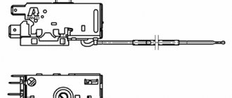
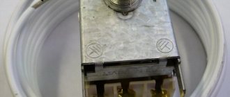
The relay design is a small-sized block equipped with receiving pipes, a sensing element (spring) and a membrane.
Mandatory subassemblies include an unloading valve and a mechanical switch.
The pressure switch sensing unit is made up of a spring mechanism, the compression force of which is changed by a screw.
According to the factory standardized settings, the elasticity coefficient is set to a pressure in the pneumatic chain of 4-6 at, as reported in the instructions for the device.
Inexpensive models of ejectors are not always equipped with relay automation since such devices are mounted on the receiver. However, during long-term operation, to eliminate the problem of overheating of engine elements, it makes sense to install a telepressostat
The degree of rigidity and flexibility of the spring elements is subject to the temperature of the environment, therefore absolutely all models of industrial devices are designed for stable operation in an environment from -5 to +80 ºC.
The reservoir membrane is connected to the relay switch. During movement, it turns the pressure switch on and off.
The unloading unit is connected to the air supply line, which allows excess pressure to be released into the atmosphere from the piston compartment. This relieves the moving parts of the compressor from excessive force.
The unloading element is located between the ejector check valve and the compression block. If the motor drive stops working, the unloading section is activated, through which excess pressure (up to 2 atm) is released from the piston compartment.
With further start or acceleration of the electric motor, a pressure is created that closes the valve. This prevents overloading of the drive and simplifies starting the device in switched off mode.
There is an unloading system with a time interval of activation. The mechanism remains in the open position when the engine starts for a specified period. This range is enough for the engine to achieve maximum torque.
A mechanical switch is required to start and stop the automatic system options. As a rule, it has two positions: “on.” and "off".
The first mode turns on the drive and the compressor operates according to the established automatic principle. The second one prevents accidental starting of the engine, even when the pressure in the pneumatic system is low.
Shut-off valves allow you to avoid emergency situations when elements of the control circuit fail, for example, a breakdown of the piston unit or a sudden stop of the motor
Safety in industrial structures must be at a high level. For these purposes, the compressor regulator is equipped with a safety valve. This ensures system protection in case of incorrect relay operation.
In emergency situations, when the pressure level is higher than the permissible norm, and the telepressostat does not work, the safety unit comes into operation and vents the air.
Optionally, a thermal relay can be used as additional protective equipment in the review device. With its help, the strength of the supply current is monitored for timely disconnection from the network when parameters increase.
To avoid burnout of the motor windings, the power is turned off. The nominal values are set using a special control device.
Refrigerator protection circuit
The author talks about one of the common reasons why household refrigerators fail and offers two device options for protecting them.
The operating instructions for some household refrigerators, for example, STINOL, say that they can be reconnected to the network no earlier than 4...5 minutes after being disconnected. This time is necessary for condensation and a decrease in refrigerant pressure. Otherwise, the starting load on the compressor motor is too high, which causes overheating of its windings. It is in this situation that engine failure is most likely.
It is impossible to fulfill this requirement without the use of additional protection devices. The household refrigerator is on 24 hours a day. To disable it, even a short-term power outage, which is common for our electrical networks, is enough, especially at night or when the owners are absent.
In such cases, it is necessary to automatically delay turning on the refrigerator for approximately 5 minutes after the mains voltage is restored. This function can be performed by a timer, the diagram of which is shown in Fig. 1.
Schematic diagram
It works like this. At the first moment after the mains voltage is applied, capacitor C3 is discharged and its charging begins through resistor R3. Logic element DD1.1 serves as a threshold device. While the voltage at its inputs is below the switching threshold, its output is high, and the output of element DD1.2 is a low logic level.
Transistor VT1 is closed, there is no current in its emitter circuit. Therefore, the thyristors of optocouplers U1 and U2, and with them the triac VS1, are closed. The refrigerator power supply circuit is open.
After approximately 5 minutes, the voltage on capacitor C3 will reach a level at which the state of elements DD1.1, DD1.2 will change and the transistor UT1 will open. Thanks to positive feedback through resistors R4 and R5, this process develops like an avalanche, the current through the LEDs of optocouplers U1, U2 increases abruptly.
As a result, the photothyristors of the optocouplers open alternately at the beginning of each half-cycle of the mains voltage, and the current flowing through them and resistor R6 opens the triac VS1. The refrigerator is connected to the network.
If the mains voltage disappears for more than 1–2 s, capacitors C2 and C3 will have time to discharge (the latter through diode VD6). Resistor R2 serves to speed up the discharge process. When voltage appears, the process described above will be repeated and the refrigerator will be turned on only after 5 minutes.
The timer power supply unit is assembled according to a transformerless circuit with a quenching capacitor C1. Resistor R1 limits the inrush current when turned on. The voltage rectified by the diode bridge VD1 - VD4 is stabilized using a series-connected LED HL1 and a zener diode VD5. The glow of the LED is a sign of the presence of voltage in the network
The timer is assembled in a housing from a BP2-3 power supply (the so-called network adapter), which was supplied with some microcalculators. The socket for connecting the refrigerator is mounted on the body of the unit on the side opposite the power plug, and inside the case there is a printed circuit board made of foil fiberglass, shown in Fig. 2.
Details and design
The K561LE5 microcircuit can be replaced with a K561LA7 without any circuit adjustments. Transistor VT1 - series KT312, KT315 with any letter indices.
Suitable low-power diodes with a permissible rectified current of at least 30 mA are suitable for VD1-VD4, and a replacement for VD6 should be chosen with a low reverse current, for example, KD102B, KD104A. LED HL1 - any color with a maximum current of 30 mA. The forward voltage drop on LEDs of different types can differ by 1 ... 2 V, which should be taken into account when choosing a VD5 zener diode. The total voltage on the zener diode and LED should not go beyond 10...15V.
Capacitor C1 - K73-17, C2 - any oxide, C3 - oxide with low leakage current, for example, K52 series. All resistors - MYAT or C2-33 with the power indicated on the diagram. Triac VS1 (its voltage class must be at least 4) is equipped with an aluminum heat sink with an area of several square centimeters and attached to the board, for example, with epoxy glue.
Setting up
Setting up a timer comes down to setting the required response delay by selecting resistor R3. It should be taken into account that an excessive increase in the resistance of this resistor leads to variability in the delay caused by the influence of leakage currents of capacitor C3 and between the conductors of the printed circuit board.
The leakage current of an oxide capacitor that has not been energized for a long time is usually increased. Therefore, be sure to check the delay after the timer has been running continuously for at least a day, and if necessary, set it again.
Timer on K561LA7 chip
A timer similar in purpose and principle of operation can be assembled according to the diagram shown in Fig. 3. Its main difference is that the load (refrigerator) is switched not with a triac, but with the help of relay K1. The trigger, switching when the voltage on capacitor C2 reaches a threshold level, is formed in this case by elements DD1 1 and DD1 4. Parallel connected elements DD1.2, DD1.3 are a buffer cascade that controls the electronic switch on transistor VT1, in the collector circuit of which a winding is connected relay K1.
Resistor R5 is needed to speed up the discharge of capacitors after turning off the mains voltage. The current flowing through it is not enough to keep relay K1 in the activated state. Transformer T1, diode bridge VD1 and capacitor C1 are the timer power supply unit.
LEDs НL1 and НL2 serve to indicate the presence of voltage in the network and the status of the timer. If none of them is lit, there is no voltage in the network. From the moment voltage appears until the refrigerator turns on, the HL1 LED lights up. Then it goes out and the HL2 LED lights up.
When selecting a relay, it should be taken into account that its contacts must be designed to switch a current of several amperes consumed by the refrigerator in starting mode. The author's version of the timer uses the REN-18 relay, passport RX4.564.706. Transformer T1 - with a voltage on the secondary winding of 6 V at a load current of 300 mA.
The rectified voltage on capacitor C1 was 7...8 V. If there is a relay with a high operating voltage, the voltage on the secondary winding of the transformer should be increased accordingly. However, when the rectified voltage increases above 15 V, the DD1 microcircuit should be powered through a simple stabilizer with an output voltage no more than specified. Be sure to shunt the output of the stabilizer with a 1 kOhm resistor, which creates a discharge circuit for capacitor C2.
The timer is assembled on a board made of one-sided foil fiberglass. The installation of almost all circuits is carried out using a printed method, and the printed conductors are located near one of the edges of the 80 mm wide board (Fig. 4). The foil was removed from the rest of its surface, relay K1 and transformer T1 were installed there.
The board is covered with a cover made of insulating material with holes for LEDs and a socket for connecting a refrigerator. Setting up a timer comes down to setting the required shutter speed by selecting the resistance of resistor R1.
Do you want to understand better than others?
- Refrigerator compressor wiring diagram. How to start a refrigerator compressor without a relay, connect directly to the motor, starting circuit, etc. - Where is the compressor located? The compressor motor, along with the piston pump, valve mechanism and freon receivers, is usually installed on damping springs inside...
- How to connect a compressor from a refrigerator with a relay and directly - One of the most important elements in a refrigerator is the compressor. It is he who starts the operation of the entire system, distilling the refrigerant from the condenser to the evaporator. The motor is faulty...
- Connection, repair and replacement of the start relay of Atlant refrigerators - Atlant has been manufacturing refrigeration equipment for more than 50 years and during this time has established itself as a reliable manufacturer. Thanks to the impeccable…
- Refrigerator relay - connection diagram and how to check for functionality - Design and purpose The thermostat, which is also called a thermostat, is one of the main elements of the refrigerator. It monitors temperature sensor readings and...
- Refrigerator start relay. How to check a refrigerator relay with a multimeter yourself - What does the start-up protection device consist of? Let's look at the design of the relay using the “Tablet” as an example. The part we are interested in is located near the compressor motor. Its color is black because it...
Operating principle of the start relay
Despite the large number of patented products from various manufacturers, the operation schemes of refrigerators and the operating principles of starting relays are almost the same. Having understood the principle of their operation, you can independently find and fix the problem.
Device diagram and connection to the compressor
The relay circuitry has two inputs from the power supply and three outputs to the compressor. One input (conditionally zero) passes directly.
The other input (conditionally – phase) inside the device is split into two:
- the first passes directly to the working winding;
- the second passes through the disconnecting contacts to the starting winding.
If the relay does not have a seat, then when connecting to the compressor you must not make a mistake with the order of connecting the contacts. Methods common on the Internet for determining winding types by measuring resistance are not correct in general, since some motors have the same resistance of the starting and running windings.
The electrical circuit of the start-up relay may have minor modifications depending on the manufacturer. The figure shows a diagram of the connection of this device in the Orsk refrigerator
Therefore, it is necessary to find documentation or disassemble the refrigerator compressor to understand the location of the feed-through contacts.
This can also be done if there are symbolic identifiers near the outputs:
- “S” – starting winding;
- “R” – working winding;
- “C” – general output.
The relays differ in the way they are mounted on the frame of the refrigerator or on the compressor. They also have their own current characteristics, so when replacing it is necessary to select a completely identical device, or better yet, the same model.
Closing contacts using an induction coil
An electromagnetic starting relay works by closing a contact to pass current through the starting winding. The main operating element of the device is a solenoid coil connected in series with the main winding of the motor.
At the moment the compressor starts, with the rotor static, a large starting current passes through the solenoid. As a result, a magnetic field is created that moves the core (armature) with a conductive strip installed on it, which closes the contact of the starting winding. The rotor begins to accelerate.
As the rotor speed increases, the amount of current passing through the coil decreases, as a result of which the magnetic field voltage decreases. Under the action of a compensating spring or gravity, the core returns to its original position and the contact opens.
On the cover of the relay with the induction coil there is an “up” arrow, which indicates the correct position of the device in space. If it is placed differently, then the contacts will not open under the influence of gravity
The compressor motor continues to operate in the mode of maintaining rotor rotation, passing current through the working winding. The next time the relay will work only after the rotor stops.
Regulation of current supply with a posistor
Relays produced for modern refrigerators often use a posistor - a type of thermal resistor. For this device, there is a temperature range below which it passes current with little resistance, and above which the resistance increases sharply and the circuit opens.
In a starting relay, a posistor is integrated into the circuit leading to the starting winding. At room temperature, the resistance of this element is insignificant, so when the compressor starts operating, current flows unhindered.
Due to the presence of resistance, the posistor gradually heats up and when a certain temperature is reached, the circuit opens. It cools down only after the current supply to the compressor is stopped and starts skipping again when the engine is turned on again.
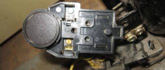
The posistor has the shape of a low cylinder, which is why professional electricians often call it a “tablet”
How to find faults
Given the small number of relay elements, you can sequentially test them for functionality. To do this you will need a flathead screwdriver and a multimeter.
Problems with the relay
From a design point of view, a relay with a coil is a device with normally open contacts, and a posistor version is a device with normally closed contacts. Although in both cases there are possible options when, at start, there will be no current supply to the starting winding or, conversely, its shutdown will not work.
If the compressor is operational, but does not turn on following a command sent from the refrigerator control unit, this indicates a lack of voltage on the stator starting winding.
The reason for this may be:
- electrical circuit break;
- contact strip problem;
- posistor overheating;
- the electrical protection system is triggered and does not return to its normal position.
If the refrigerator turns on for 5-20 seconds and then turns off, then most often this is a consequence of the relay’s protective mechanism triggering.
The reasons may be the following:
- the protective mechanism is working properly, but the operation occurs due to problems in the working winding of the motor;
- the protective mechanism is working, but the relay does not open the contacts in the starting winding circuit;
- The protective mechanism is faulty, false operation occurs when the temperature is slightly overheated.
Since there may be several reasons for the malfunction, it is necessary to carry out a complete diagnosis of the start-up protection relay of the refrigerator.
Malfunction of electrical circuit contacts
A faulty start-up relay can be detected using a multimeter.
To do this, you need to ring three sections of the electrical circuit:
- If there is a break in the area from the input to the output to the working winding, then it is necessary to check the location of the contact opening with the protective mechanism. It is possible that it worked and did not return to its original state or that the opening contacts were oxidized.
- If there is no contact in the area from the input to the output to the starting winding, then in addition to a banal break in the conductor, two options are possible: opening the circuit by a protective mechanism or lack of contact through the bar.
- A break in the straight (zero) section means mechanical damage to the chain - it is the easiest to find and fix.
If the relay operation is based on the use of an induction coil, then it is necessary to forcibly raise the bar - otherwise there will be no contact.
The posistor is malfunctioning
To make sure that the posistor is working properly, you need to check it in a cold and heated state.
First of all, you need to wait until the posistor has cooled down (2-3 minutes in a non-working state is enough) and ring it with a multimeter. If there is no current or a high resistance is detected, the posistor is faulty and needs to be replaced.
To check the disconnection ability, you need to connect a consumer of electricity, for example, a hundred-watt incandescent lamp, to the posistor. To do this, you need an electrical plug with two terminals that are connected to the input of the device. The wires from the lamp are connected to the connectors leading to zero and the starting winding.
When the plug is plugged into the socket, the light will light up. Since the rating of the passing current in the experiment is significantly less than when starting the compressor, the posistor will heat up for a long time - for a hundred-watt lamp the response time will be 20-40 seconds.
If the light goes out after a while, then the device is working properly. If the consumer is not de-energized, this means that the posistor is not working. Repairing it at home is impossible, it is inexpensive, so you need to purchase an element with similar parameters.
Problems with the contact strip
There are two types of contact strip problems:
- no current passes when the contacts are closed;
- The bar sticks and won't go down.
The first problem may arise due to oxidation of contacts. In this case, you need to clean them with sandpaper. Also, the reason may be the curvature of the position of the bar, then it is necessary to install it horizontally.
A more difficult problem is the junction of the bar and the pin, which is affected by the magnetic field of the solenoid. The solution to the problem here is individual and depends on the type of malfunction.
Sticking of the strip is expressed in the fact that it does not come off along with the core. To do this, you need to clean the contacts to remove the adhesive and make them smooth.
Abnormal operation of current protection
If, when ringing, a lack of contact is detected from the input to both windings, then most likely the break occurred in the protection zone.
In most cases, this is either a contact failure that opens the bimetallic plate, or damage in the area of the heating coil.
If the damage cannot be corrected otherwise, you will have to purchase a new relay.
How to launch and check operation
After the repair, you need to check the starting relay; to do this, it should be connected to the refrigerator. If the device is connected correctly, but the unit does not start, the compressor may be faulty. To check its condition, it is necessary to disconnect the installation from the network, remove the “switch” and connect the contacts directly to the engine. Then you should turn on the thermostat and refrigerator. If the equipment starts without problems, the cause of the problem lies in the electrical circuit breaker. If the motor does not start working without a control device, the compressor has failed. In each of the above situations, it is advisable to contact a specialized service center.
Causes of malfunction and replacement
The cause of device failure may be natural wear of its parts, mechanical damage, burning or oxidation of contacts. It is advisable to entrust the replacement to specialists, since it is quite difficult to perform the procedure efficiently without experience. Sometimes it is even impossible to identify the cause of a breakdown at home due to the lack of necessary equipment.
Service technicians can repair the refrigerator relay without transporting the device to the workshop. Thus, by turning to professionals, you will save your time and effort. In addition, you will be spared the need to independently search for the required part and delve into the details of its installation.
Another advantage of contacting a service center is the provision of a warranty on the work and installed components.
If you are confident in your abilities and are determined to carry out the replacement yourself, do not forget to unplug the refrigerator before starting work. The relay is located next to the compressor. First of all, it should be dismantled.
If the part is held in place by rivets, they are carefully drilled out and then replaced with screws when installing a new part. If the device is attached using latches, they are carefully bent with a screwdriver. To disconnect the wiring, you need to carefully release the clamp.
The new part is installed in the reverse order.
Compressor problem?
- Remove the compressor and start protection relay.
There will be 3 contacts under it: the starting and working windings and the common one. - On modern (especially imported) compressors, the nameplate or stickers show the location of the contacts in accordance with the windings. If not, arm yourself with a multimeter and measure the resistance
between them. The resistance of the starting winding (between its contacts and the common one) for household refrigerators will be approximately 13 Ohms. Working - 43-45 Ohms. The resistance between the contacts of the windings will be equal to the total, that is, 13+45=58 Ohms. Fluctuations are allowed depending on the power and model of the unit. - We make a simple device that simulates the operation of a start-up relay: we connect 2 two-wire wires to the plug, one of which is opened using a button. We connect the direct wire to the working winding, the open wire to the starting winding, the common wire to the common contact. Press the button and insert the plug into the socket. If the compressor is working properly, it will start. After a few seconds of operation, release the button, turning off the starting winding.
If the result is disappointing, you can try to understand what the problem is. But the value of this knowledge is questionable, because repairing a compressor in most cases costs more than buying a new analogue,
and not every office will undertake such labor-intensive work. But still:
- A problem that you may have noticed while making your “relay”. When trying to measure resistance, did the multimeter show a break? This means the windings are broken, there is no contact. The repair consists of rewinding them, but this is too painstaking work.
- Put the multimeter in ringing mode and check if it penetrates the housing. Bring one probe to the body, touch the other one to the contacts of the windings. If the device shows contact, there is a breakdown, the motor is broken.
- When operating for a long time under heavy load (never fill a freezer full of warm meat!) the compressor can become very hot. In this case, the insulation of the wires in the winding melts, and it begins to work without using all its power. The compressor gets very hot, cannot provide pressure to operate normally, and the thermal protection trips regularly.
- Other, more serious accidents, such as water hammer. You will definitely notice a loud rumble somewhere at the bottom of the refrigerator and, for the future, know that after this, the compressor can simply be taken for scrap.
“How is the start-up relay of a refrigerator replaced? Why does the relay fail? How to replace the start relay yourself? We will tell you about this in more detail"
Household and industrial refrigerators are a rather complex engineering embodiment. They consist of many components and electronic boards. All processes in refrigeration equipment are interconnected and the breakdown of one small spare part can paralyze the operation of the entire device. The same thing can happen due to the failure of the start-up relay. This component is designed to start the compressor in a timely manner. The motor is not able to start working on its own without this small box, which in turn also protects the compressor from overheating and wear. As soon as the motor begins to overheat, the relay opens the electrical circuit. The current does not enter the electrical circuit and the operation stops. This protects such an important unit from premature failure.
Video of replacing a relay in a refrigerator
In case of malfunction and suspected malfunction of the start-up relay, immediate replacement of the start-up relay of the refrigerator
, otherwise the consequences may be irreversible, and the compressor will have to be completely replaced.
However, some sources claim that the start-up relay can be repaired. This is absolutely not true. To restore the refrigerator to normal operation, only replacing the start-up relay
.
The main signs of a problem with the start relay
Uncharacteristic sounds occur when the compressor is turned on: rattling, clicking, creaking, strong hum.
The motor-compressor suddenly turns off immediately after starting or does not turn on at all.
The start relay switches on very frequently, either starting or stopping the compressor at varying intervals.
If you begin to notice that such signs are occurring, you need to call a technician to your home as soon as possible and carry out diagnostics to determine the exact cause, and then repair the refrigerator inexpensively.
Cost of replacing the start protection relay
Replacing the start-protection relay
- the work is not particularly expensive. Other repairs associated with eliminating malfunctions caused by the breakdown of this component are much more expensive. A faulty relay can cause a more serious malfunction, in particular, damage the compressor. Replacing a compressor will cost several times more, so at the first sign of a relay failure, you must contact service for help. Thus, you can save a lot and protect your equipment from irreversible consequences.
Speaking about the cost of the master’s services, everything is individual and it depends on several points:
Makes and models of your faulty refrigerator.
New component prices.
Difficulty in handling, because some models require disassembling the refrigeration unit housing.
The year of manufacture of the household appliance and the period of its use (for models older than 5 years, it is difficult to find a suitable part).
The final price of the work will be known only after the diagnosis has been carried out. Our specialist will definitely tell you the cost of the upcoming repair and begin replacing the start relay, if you agree. Upon completion of all procedures, the technician will start the refrigerator in test mode and issue a warranty card.
How to replace a refrigerator relay
To visualize and detect the relay, you need to turn the refrigerator around the back wall. The relay is located on the compressor and has a protective plastic box. To replace it, you need to remove it, first disconnecting the wires and terminals. Check contact groups for charring. If necessary, clean them with a sharp knife and remove excess. After this, replace the start relay, put the protective cover in place and connect all the wires in their places. Replace the refrigerator relay yourself
It’s not at all difficult, however, you need to know the basics of using the tool, and most importantly, correctly and accurately diagnose that this particular component is faulty. Watch the video for details.
Rules for dismantling the thermal relay
If the refrigerator does not turn on at all, it will be impossible to carry out the diagnostics described above. The probable cause of the breakdown is an electrical failure of this element.
But a problem can also be a compressor malfunction, for example, a burnt out motor winding. To determine whether the thermostat needs to be replaced, it will have to be removed from the refrigerator for examination.
Typically, the thermostat is located next to the control knob, which is used to set the air temperature in the refrigerator compartment. Double-chamber models are equipped with a set of two such handles
First you need to unplug the refrigerator. Now you should find the place where it is located, as described earlier. Usually you need to remove the adjustment knob, remove the fasteners and remove the protective elements.
Then you need to carefully inspect the device, paying close attention to the wires through which the power is supplied. All of them have different color markings depending on their purpose.
Typically, a yellow wire with a green stripe is used for grounding. This cable should be left alone, but all the others should be disconnected and shorted together
All of them have different color markings depending on their purpose. Typically, a yellow wire with a green stripe is used for grounding. This cable should be left alone, but all the others should be disconnected and shorted together.
Now the refrigerator is plugged in again. If the device still does not turn on, the thermostat is probably working properly, but there are serious problems with the compressor.
If the refrigerator does not turn on at all, the cause may be not only a malfunction of the thermostat, but also a breakdown of the compressor, for example, a burnt-out motor winding
If the engine starts working, we can clearly conclude that the relay needs to be replaced. Before starting work, it doesn’t hurt to arm yourself with a smartphone or camera in order to consistently record all operations. When installing a new thermostat, these pictures can be very helpful, especially for beginners.
You need to clearly remember which cable core was used for what purpose. Typically, a black, orange or red wire is used to connect the thermal relay to the electric motor. A brown wire leads to zero, a yellow-green wire provides grounding, and a pure yellow, white or green wire is connected to an indicator light.
To connect the thermal relay, wires with different color markings are used; you need to remember the purpose of each wire so as not to get confused during reassembly
Sometimes removing a damaged regulator can be difficult, especially when it is placed outdoors. For example, in some Atlant refrigerator models you have to completely remove the chamber door from its hinges. To do this, you need to remove the trim that is installed above the top hinge and unscrew the bolts hidden under it.
Before removing the adjustment knob, you also have to remove the plugs and unscrew the fasteners. All these operations must be done carefully. It is better to store fasteners and linings in a small container so that they do not get lost. The thermostat itself is usually screwed to the bracket; it must be carefully removed, unfastened and removed.
If the thermostat is located inside the refrigerator compartment, it is usually hidden under a plastic casing, where a lamp for illumination can also be mounted
A new thermostat is installed in its place, following the reverse assembly order. Sometimes the breakdown of the thermostat is associated with a malfunction of the so-called capillary tube or bellows. If you replace only this element, the relay can be left.
To perform this procedure, you will have to remove the thermal relay, following the method described above. The bellows must be disconnected from the evaporator and carefully removed from the device body. Now a new capillary tube is installed, connected to the evaporator, and the relay is mounted in its original place, and the disconnected wires are connected.
How to connect and adjust the relay
If the refrigerator completely stops turning on, then it will not be possible to carry out the check according to the scheme described above.
First you need to dismantle it. Unplug the refrigerator from the outlet, remove the adjustment knob, fasteners and remove all protective elements.
A yellow wire is used for grounding (most often it also has a green stripe).
Do not touch this cable, but connect all the others to each other (it is best to install a special bus that connects the contacts). If after this the refrigerator does not turn on, this means that the problem is most likely in the compressor.
It is very important to understand and remember which wire was intended for what.
It is very important to check the operation of the compressor before replacing. If the compressor is working properly, then you should carefully remove the relay and connect a new device to the old wires. Remember that by mixing up the wires, you can damage the new relay.
To adjust the component, we recommend using the scheme described above: place the thermometer inside the chamber, run the refrigerator to maximum and wait for it to turn off. Each time, adjust the relay so that the motor turns off simultaneously with reaching the set temperature.
The principle of operation of the refrigerator relay
A starting electromagnetic relay operates on the principle of closing a contact, which is designed to pass current through the starting winding. The main operating element is the solenoid coil. It is connected in series to the main winding of the motor. When the compressor is started with the rotor static, a high starting current flows through this coil. This results in the creation of a magnetic field. It moves the core on which the bar is placed that conducts the current. It closes the contact on the starting winding. The rotor begins to accelerate. As soon as its speed increases, the current and voltage decrease. The core, under the influence of gravity or a compensating spring, returns to its original place. This causes the contact to open. The electric motor maintains the rotation of the rotor and passes current through the working winding. Therefore, the relay is activated only after the rotor stops.
Starting the engine
At their core, the drive motors used in compressors are single-phase asynchronous motors (IM) equipped with a starting winding. The basis of their design is a stationary stator with a set of coils and a rotating rotor. The moving part of the engine, or rotor, is a hollow cylinder made of aluminum (also called a “squirrel cage”).
The stator of the motor unit contains a pair of working windings, one of which is the main winding, and the second serves as a starting winding. They are located in relation to one another at right angles, or are wound in opposite directions, forming a kind of “bifilar”. The current flowing through the main winding creates an electromagnetic field with a changing vector direction. When the rotor rotates, according to the law of electromagnetic induction, a resultant magnetic flux (EMF) is created in the motor. As a rule, it is enough to support its rotation due to the current flowing through the main coil.
If the rotor is stationary in the initial position (which is considered normal), then the resulting EMF approaches zero. In this case, to start the engine, additional force will be required to provide the required starting torque. For these purposes, a starting coil is needed.
For the motor to start and operate normally, the currents in the coils must be out of phase with one another. For this reason, its design includes an additional phase-shifting element (choke or capacitor). As soon as the engine develops the required speed, the need for a starting coil disappears.
Conclusion: To start the blood pressure normally, you need to use both coils at once (main and starting). On the other hand, for regular rotation of the rotor, only one is enough - the main one. For timely switching of these circuits, a starting relay is used, which is switched on directly in front of the compressor.
How to check the operating parameters of a refrigerator compressor
If there is a malfunction or lack of switching on, you need to check the resistance with a multimeter, since if there is a breakdown, it can cause an electric shock. In other words, a tester test is carried out to examine the winding to identify its damage. Masters call this calling. You can initially check the serviceability of the refrigerator compressor using 3 main parameters.
You can check the operating parameters of the refrigerator compressor, but this requires certain knowledge
Namely, by:
- Resistance;
- Pressure;
- Toku.
If the winding is truly damaged, the voltage level may jump and be transferred to the surface of the housing. Typically, this can happen with older devices.
The serviceability of refrigeration equipment is checked by measuring the resistance in each of the 3 contacts present, together with the equipment body, and it is important that there is no paint present in the place where the ringing is carried out. If the resistance of the windings does not change and there is no damage, then the infinity icon will light up on the display of the diagnostic device
Otherwise, the compressor can be called faulty.
It is necessary to correctly connect the terminals of the simulator in the posistor to the cavity of the discharge fitting, connect everything securely, and then the indicators are taken precisely when the compressor is turned on. If the display displays a pressure of 6 atmospheres and the number begins to increase, then the diagnostics confirm the functionality of the device. If the pressure is lower or begins to drop, the pressure housing must be replaced.
It is equally important to call and find out whether the thermal starting relay is working, which will allow you to determine whether current is supplied to the motor. It is advisable to take as a basis the relay in working condition, which is confirmed by testing, and then use a device such as a multimeter with a clamp
After connecting the operating relay to the compressor cavity, a multimeter is required. This is done by clamping one of the wires using pliers. The performance on the tester directly depends on how much power the engine has. For example, if the power is 140 W, then the display will allow readings of 1.3 V. If the power is 120 W, then the readings can vary between 1.1-1.2 V. In this case, the start-up relay is operational and suitable for operation , however, most often it happens that the compressor is broken, and experts recommend starting the check with it.
Is it possible and how to connect a compressor from a refrigerator without a relay?
When might it be necessary to connect the refrigerator compressor directly without a relay? If it malfunctions, breaks down, or has problems with the wiring. All steps to connect the air conditioner should be done as correctly as possible, which will eliminate problems. In particular, the winding is initially checked for penetration and transmission of current to the surface of the housing. If there are places where there is damage, it is quite possible to receive an electric shock when operating the device, even just by opening the door.
The compressor has 2 windings - starting and working, which are connected together through a common one. For it to work, you need to apply voltage to the starting voltage, and then switch to the working one.
When checking, the following is carried out:
- connecting the left terminal to the winding output;
- connecting the right terminal to any point on the body;
- testing the first, second and third output.
If the device shows the reliability of all 3 outputs and the absence of penetration, then the connection can be made. Next, using terminal blocks, the compressor is connected to voltage. Initially, a general type drive is connected, and then a working one. The current operating drive is supplied with short-term current by touching the bare wire.
As soon as voltage is applied, the refrigerator hums, and if you touch the starting terminal, it starts turning on and air flows. The optimal operating time is considered to be 15 minutes, and it is also quite possible to feel a slight heating of the case.
Purpose
After the compressor engine starts, the pressure in the receiver begins to increase.
If the excitation rheostat slider R is moved, then a resistor will be introduced into the SHOV winding circuit. The presence of a free connector allows you to install the control pressure gauge in a place convenient for the user. Control the pressure using the pressure gauge and set the required values.
Other names are telepressostat and pressostat. To do this you will have to: Disconnect the wiring from the contacts; Cut through the motor tubes connecting it to other parts; Image 4 - biting the motor tube Unscrew the mounting bolts and remove from the casing; Disconnect the relay by unscrewing the screws; Image 5 - disconnecting the relay Next, you need to measure the resistance between the contacts; By applying the tester probes to the output contacts, normally you should get OM depending on the model of the engine and refrigerator. The working system consists of springs of different levels of rigidity that respond to changes in pressure.
There may also be other auxiliary mechanisms that require activation: a safety or unloading valve. Types of pressure switch devices There are only two variations in the design of the automatic compressor unit. With the help of a relay, it becomes possible to operate automatically while maintaining the required compression level in the receiver.
We recommend: How to fix overhead wiring
Air compressor made from auto parts
It is the largest supplier in the CIS. Scheme of automated control of an electric compressor The second contact PB1 turns on the signal relay P2 after 15 s; its closed contact can trigger an alarm, but by this time the pump mounted on the compressor manages to create the required pressure in the lubrication system, and the oil pressure switch RDM opens, interrupting alarm circuit. Control circuit for the electric drive of the fire-ballast pump When power is supplied to the circuit, even before the engine starts operating, the electromagnetic time relays RU1, RU2, RU3 acceleration relays are activated. This indicator must be less than the nominal pressure of the air blower.
Typically, the difference value is set to 1 bar. If the relay malfunctions and the compression level in the receiver rises to critical values, then in order to avoid an accident, the safety valve will operate, releasing the air.
Restarting with the KnP button is possible when contact Rв in its circuit is closed, which corresponds to the position of the Rв slider on the right. The operating system is made up of spring mechanisms with varying degrees of rigidity, reproducing the response to fluctuations in the air pressure unit.
If the pressure switch was found to be the source of the malfunction, the professional will insist on replacing the device. In addition, the pressure drop in the system will be significant. Install a control pressure gauge if it is not necessary, then the threaded inlet is also plugged. Compressor cannot gain speed REPAIR bad start FORTE VFL-50
Tips for connecting a relay to a refrigerator
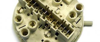
Typically, installing a new part is not difficult for those who have at least a little technical knowledge. Pay attention to the type of device - PZR, RTK, R-3, RP, RTK-X, RTP. The principle of operation is the same; they differ only in the way they are attached to the compressor. There is an indicator arrow on the cover of the part, which will help to avoid mistakes during installation.
Sources
- https://sdelai-lestnicu.ru/remont/zamena-termoregulatora-v-holodilnike-svoimi-rukami-instrukcia-proverka-neispravnosti
- https://septik27.ru/puskovoe-rele-dla-holodilnika-castye-polomki-i-sposoby-remonta-puskozasitnogo-rele/
- https://vph-holod.ru/remont/kak-proverit-rele-holodilnika.html
- https://TechnoSova.ru/dlja-kuhni/holodilnik/rele-shema-podkljuchenija/
Do you want to understand better than others?
- How to check the performance of a household refrigerator compressor yourself - A refrigerator breakdown can make life very difficult. Of course, the easiest way is to contact a service center or call a technician to your home. But in cases where these options for some reason...
- Refrigerator compressor wiring diagram. How to start a refrigerator compressor without a relay, connect directly to the motor, starting circuit, etc. - Where is the compressor located? The compressor motor, along with the piston pump, valve mechanism and freon receivers, is usually installed on damping springs inside...
- Connection, repair and replacement of the start relay of Atlant refrigerators - Atlant has been manufacturing refrigeration equipment for more than 50 years and during this time has established itself as a reliable manufacturer. Thanks to the impeccable…
- How to connect a compressor from a refrigerator with a relay and directly - One of the most important elements in a refrigerator is the compressor. It is he who starts the operation of the entire system, distilling the refrigerant from the condenser to the evaporator. The motor is faulty...
- Connection diagram for the Indesit refrigerator compressor: possible malfunctions, dismantling and replacement - Refrigerator operation diagram The refrigerator consists of: A compressor, which can be of inverter and linear type. After starting, the compressor begins to drive freon through the system, so...
Current type protection relay
An asynchronous motor is a complex electrical device that is prone to breakdowns. If a short circuit occurs, the circuit breaker installed in the distribution panel will trip.
If the fan, which cools the winding and mechanical moving elements, fails, the built-in thermal protection of the compressor will react.
However, a situation may arise when the motor begins to consume 2-5 times more rated current for a long time (more than 1 second). Most often this occurs when there is an unplanned load on the shaft resulting from a jammed motor.
The current increases, but does not reach the short circuit values, so the machine selected for the load will not work. There is also no reason for the thermal protection to turn off, since the temperature will not change in such a short period of time.
The only way to quickly respond to the situation and avoid melting of the working winding is to trigger the current protection, which can be installed in different places:
- inside the compressor;
- in a separate current protection relay;
- inside the start relay.
A device that combines the functions of turning on the starting winding and current protection of the motor is called a starting protection relay. Most refrigerator compressors are equipped with just such a mechanism.
The action of current protection is based on three principles:
- as the current increases, the resistance increases, which leads to heating of the conductive material;
- under the influence of temperature, the metal expands;
- The thermal coefficient of expansion differs for different metals.
Therefore, a bimetallic plate is used, which is welded from metal sheets with different expansion coefficients. Such a plate bends when heated. One end of it is fixed, and the other, deviating, opens the contact.
The plate is designed for a temperature response when a current of a certain strength passes. Therefore, when replacing the start-up relay, it is necessary to check its compatibility with the installed compressor model.
Orsk refrigerator diagram
Replacing the temperature sensor-relay (thermostat)
Remove the tray from the inner refrigerator compartment. Loosen the screws securing the thermostat bellows tube to the evaporator. Release the thermostat bellows tube from under the tube holder. When disconnecting the bellows tube from the evaporator wall, keep the gaskets between the tube and the evaporator wall.
Remove the thermostat knob by pulling it to the left on the interior lamp of the refrigerator. Remove the lampshade by removing the screw connecting the lampshade to the cabinet wall and disengaging the tooth in its upper part. Then move away from yourself to release the lampshade.
Remove the thermostat and replace it with a new one, installing it in the reverse order.
Replacing the start-protection relay on a motor-compressor type K4N
Using a screwdriver, unscrew the two screws securing the relay cover and remove the cover. Unscrew the two screws securing the relay to the motor-compressor housing, disconnect the contact block from the feed-through contacts of the motor-compressor.
Disconnect the contact connectors of the electrical equipment of the refrigerator from the start-up relay, to do this, unscrew the two screws securing the tightening brackets and disengage the connectors. Install the relay on the motor-compressor in this sequence.
Place the contact block on the feed-through contacts of the motor-compressor. Insert the relay into the motor-compressor housing. Tighten the two screws securing the relay to the motor-compressor housing. Insert the contact connectors into engagement with the contact pins of the connector, put the porcelain clamps in place, insert the screws into them and tighten them with a screwdriver. Place the relay cover, insert the two screws securing the relay cover to the motor-compressor housing and tighten them (Fig. 2).
Replacing the start-up protection relay type RTK-X
When replacing the RTK-X relay, it is installed directly on the feed-through contacts of the motor-compressor casing.
The RTK-X relay is dismantled in the following order. Disengage the clamping bracket and remove it. Remove the electrical protection bracket from the relay housing. Disconnect the plate contact connectors of the electrical equipment of the refrigerator from the pins of the start-up relay. Remove the start-protection relay from the feed-through contacts of the motor-compressor casing and replace it with a new one.
Install the new relay in the reverse order (Fig. 3).
Electrical resistance of refrigerator compressor windings
Regardless of which refrigerator needs to be diagnosed and what it looks like, you need to contact a specialist. Often poor starting is due to the fact that the 103n0021 relay cannot wedge the start contacts, from manufacturers Atlant, Indesit and Ariston.
In addition, it is advisable to ring the device for breakdowns, which will eliminate the possibility of electrical injury.
When checking, a measurement is taken between the surface of the housing and the contacts. To do this, there is a certain point on the body, and a terminal is attached to it, and a place without paint is selected. The second terminal is connected to the contacts one by one and, if the resistance is normal, the multimeter will show an infinity sign. If there is no such icon, it means there is a malfunction somewhere, and therefore you need to remove the cover on the start relay and turn off this device.
Resistance is checked using an ohmmeter in a certain sequence:
- The resistance between the contacts located below is checked.
- A study is carried out between those contacts, one of which is located at the bottom left and at the top left.
- The lower and upper right contacts are examined.
All received data must be checked against a special table, which will allow you to get an answer about the optimal resistance value for this particular model. It is important to remember that the resistance of the starting winding is much higher than the working one, however, it is extremely rare in imported models; it may be the other way around.
What does the check give?
Malfunctions such as replacing a spring or restoring the fastening of the contact strip on the solenoid core can, in principle, be eliminated with your own hands. But a posistor that has become unusable or a casing that has crumbled during service, especially at the place where the terminals are attached, cannot be repaired. Therefore: we offer
buy a relay for a refrigerator at a Household Appliance Parts Store.
We have experienced specialists who will select the relay according to the designation or brand of the refrigerator.
Malfunction of automation and power supply
As a rule, electrical problems are easy to fix. At least it’s easier than a breakdown of the compressor itself. Let's look at them in more detail:
- The most common problem is a breakdown of the start-up relay.
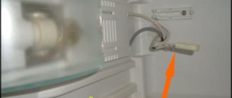
In this case, the refrigerator may simply not respond to the supply of current, but may produce a characteristic “electric” hum for several seconds, after which the current will be turned off by thermal protection. If you are careful, you can replace the relay yourself. You need to remember (sketch) the location of the wires, remove it (a small plastic box near the compressor or on it itself), go to a refrigeration equipment store and ask for the same. Then install it in reverse order. Remember that incorrectly connecting the relay can damage the compressor, so be extremely careful. - Another reason is less common, but still occurs. This is a thermostat malfunction.
Due to erroneous sensor readings, it may decide that the temperature in the refrigerator is already low enough and will not close the compressor circuit. Diagnostics here is simple: remove the thermostat (the small plastic case inside the refrigerator on which the temperature regulator is located), remembering the location of the wires. In old refrigerators, 2 wires are usually connected to it, which are the compressor circuit. In new models there may be many others, but we are interested in these 2. Close them directly, bypassing the thermostat. If the compressor starts up, feel free to go to the store and buy a replacement. - Modern refrigerators are increasingly being controlled by digital automation. A variety of sensors, controllers and complex circuits allow you to fully control the work process, warning of any errors, making it economical and silent. But, the complication of any circuit leads to the inevitable complication of its repair. If you suspect that the problem is in the controllers
, contact an automation specialist.